Contact Us: 800-387-5335
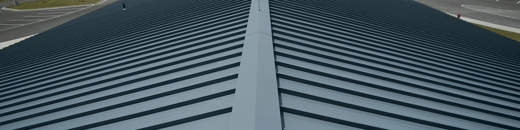
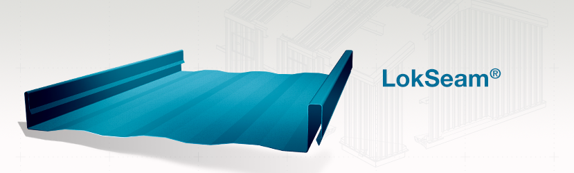
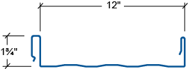
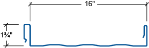
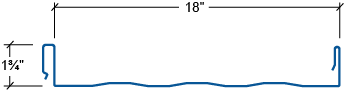
LokSeam® is a snap-together standing seam roof system with a 1 3/4″ tall vertical rib, for use on roofs with a minimum slope of 3:12. LokSeam® panels are available in 12-inch, 16-inch and 18-inch widths. LokSeam® panels can be installed over open framing or a solid substructure and are capable of transitioning from roof to fascia with the use of a rib cover.
Advantages
Attributes
LokSeam® Panel 12″ – Section Properties
| NEGATIVE BENDING | POSITIVE BENDING | |||||||
| Panel Gauge | FY (KSI) | WEIGHT (PSF) | Ixe (IN.4/FT.) | Sxe (IN.3/FT.) | Maxo (KIP-IN.) | Ixe (IN.4/FT.) | Sxe (IN.3/FT.) | Maxo (KIP-IN.) |
| 24 | 50 | 1.41 | 0.0472 | 0.0597 | 1.7888 | 0.0952 | 0.0682 | 2.0419 |
| 22 | 50 | 1.81 | 0.0625 | 0.0850 | 2.5446 | 0.1233 | 0.0909 | 2.7222 |
LokSeam® Panel 16″ – Section Properties
| NEGATIVE BENDING | POSITIVE BENDING | |||||||
| Panel Gauge | FY (KSI) | WEIGHT (PSF) | Ixe (IN.4/FT.) | Sxe (IN.3/FT.) | Maxo (KIP-IN.) | Ixe (IN.4/FT.) | Sxe (IN.3/FT.) | Maxo (KIP-IN.) |
| 24 | 50 | 1.34 | 0.0353 | 0.0452 | 1.3527 | 0.0758 | 0.0519 | 1.5563 |
| 22 | 50 | 1.71 | 0.0500 | 0.0665 | 1.9938 | 0.1052 | 0.0731 | 2.1906 |
LokSeam® Panel 18″ – Section Properties
| NEGATIVE BENDING | POSITIVE BENDING | |||||||
| Panel Gauge | FY (KSI) | WEIGHT (PSF) | Ixe (IN.4/FT.) | Sxe (IN.3/FT.) | Maxo (KIP-IN.) | Ixe (IN.4/FT.) | Sxe (IN.3/FT.) | Maxo (KIP-IN.) |
| 24 | 50 | 1.25 | 0.0321 | 0.0403 | 1.2066 | 0.0682 | 0.0465 | 1.3906 |
| 22 | 50 | 1.60 | 0.0446 | 0.0594 | 1.7795 | 0.0950 | 0.0655 | 1.9607 |
Allowable Uniform Loads In Pounds Per Square Foot – 12″ Panel
| 24 Gauge (Fy = 50 Ksi) | ||||||||
| SPAN TYPE | LOAD TYPE | SPAN IN FEET | ||||||
| 2.5 | 3.0 | 3.5 | 4.0 | 4.5 | 5.0 | 5.5 | ||
| SINGLE | LIVE LOAD | 200.0 | 151.3 | 111.1 | 85.1 | 67.2 | 54.5 | 45.0 |
| 2-SPAN | LIVE LOAD | 190.8 | 132.5 | 97.3 | 74.5 | 58.9 | 47.7 | 39.4 |
| 3-SPAN | LIVE LOAD | 200.0 | 165.5 | 121.7 | 93.2 | 73.6 | 59.6 | 49.3 |
| 4-SPAN | LIVE LOAD | 200.0 | 154.6 | 113.6 | 87.0 | 68.7 | 55.7 | 46.0 |
| 22 Gauge (Fy = 50 Ksi ) | ||||||||
| SPAN TYPE | LOAD TYPE | SPAN IN FEET | ||||||
| 2.5 | 3.0 | 3.5 | 4.0 | 4.5 | 5.0 | 5.5 | ||
| SINGLE | LIVE LOAD | 200.0 | 200.0 | 148.1 | 113.4 | 89.6 | 72.6 | 60.0 |
| 2-SPAN | LIVE LOAD | 200.0 | 188.5 | 138.5 | 106.0 | 83.8 | 67.9 | 56.1 |
| 3-SPAN | LIVE LOAD | 200.0 | 200.0 | 173.1 | 132.5 | 104.7 | 84.8 | 70.1 |
| 4-SPAN | LIVE LOAD | 200.0 | 200.0 | 161.6 | 123.7 | 97.8 | 79.2 | 65.5 |
The engineering data contained herein is for the expressed use of customers and design professionals. Along with this data, it is recommended that the design professional have a copy of the most current version of the North American Specification for the Design of Cold-Formed Steel Structural Members published by the American Iron and Steel Institute to facilitate design. This Specification contains the design criteria for cold-formed steel components. Along with the Specification, the designer should reference the most current building code applicable to the project jobsite in order to determine environmental loads. If further information or guidance regarding cold-formed design practices is desired, please contact the manufacturer. EFFECTIVE JANUARY, 2014 SUBJECT TO CHANGE WITHOUT NOTICE
Allowable Uniform Loads In Pounds Per Square Foot – 16″ Panel
| 24 Gauge (Fy = 50 Ksi) | ||||||||
| SPAN TYPE | LOAD TYPE | SPAN IN FEET | ||||||
| 2.5 | 3.0 | 3.5 | 4.0 | 4.5 | 5.0 | 5.5 | ||
| SINGLE | LIVE LOAD | 166.0 | 115.3 | 84.7 | 64.8 | 51.2 | 41.5 | 34.4 |
| 2-SPAN | LIVE LOAD | 144.3 | 100.2 | 73.6 | 56.4 | 44.5 | 36.1 | 29.8 |
| 3-SPAN | LIVE LOAD | 180.4 | 125.3 | 92.0 | 70.5 | 55.7 | 45.1 | 37.3 |
| 4-SPAN | LIVE LOAD | 168.4 | 116.9 | 85.9 | 65.8 | 52.0 | 42.1 | 34.8 |
| > 22 Gauge (Fy = 50 Ksi ) | ||||||||
| SPAN TYPE | LOAD TYPE | SPAN IN FEET | ||||||
| 2.5 | 3.0 | 3.5 | 4.0 | 4.5 | 5.0 | 5.5 | ||
| SINGLE | LIVE LOAD | 200.0 | 162.3 | 119.2 | 91.3 | 72.1 | 58.4 | 48.3 |
| 2-SPAN | LIVE LOAD | 200.0 | 147.7 | 108.5 | 83.1 | 65.6 | 53.2 | 43.9 |
| 3-SPAN | LIVE LOAD | 200.0 | 184.6 | 135.6 | 103.8 | 82.0 | 66.5 | 54.9 |
| 4-SPAN | LIVE LOAD | 200.0 | 172.4 | 126.6 | 97.0 | 76.6 | 62.1 | 51.3 |
The engineering data contained herein is for the expressed use of customers and design professionals. Along with this data, it is recommended that the design professional have a copy of the most current version of the North American Specification for the Design of Cold-Formed Steel Structural Members published by the American Iron and Steel Institute to facilitate design. This Specification contains the design criteria for cold-formed steel components. Along with the Specification, the designer should reference the most current building code applicable to the project jobsite in order to determine environmental loads. If further information or guidance regarding cold-formed design practices is desired, please contact the manufacturer. EFFECTIVE JANUARY, 2014 SUBJECT TO CHANGE WITHOUT NOTICE
Allowable Uniform Loads In Pounds Per Square Foot – 18″ Panel
| 24 Gauge (Fy = 50 Ksi) | ||||||||
| SPAN TYPE | LOAD TYPE | SPAN IN FEET | ||||||
| 2.5 | 3.0 | 3.5 | 4.0 | 4.5 | 5.0 | 5.5 | ||
| SINGLE | LIVE LOAD | 148.3 | 103.0 | 75.7 | 57.9 | 45.8 | 37.1 | 30.6 |
| 2-SPAN | LIVE LOAD | 128.7 | 89.4 | 65.7 | 65.7 | 50.3 | 32.2 | 26.6 |
| 3-SPAN | LIVE LOAD | 160.9 | 111.7 | 82.1 | 62.8 | 49.7 | 40.2 | 33.2 |
| 4-SPAN | LIVE LOAD | 150.2 | 104.3 | 76.6 | 58.7 | 46.4 | 37.6 | 31.0 |
| 22 Gauge (Fy = 50 Ksi ) | ||||||||
| SPAN TYPE | LOAD TYPE | SPAN IN FEET | ||||||
| 2.5 | 3.0 | 3.5 | 4.0 | 4.5 | 5.0 | 5.5 | ||
| SINGLE | LIVE LOAD | 200.0 | 145.2 | 106.7 | 81.7 | 64.5 | 52.3 | 43.2 |
| 2-SPAN | LIVE LOAD | 189.8 | 131.8 | 96.8 | 74.1 | 58.6 | 47.5 | 39.2 |
| 3-SPAN | LIVE LOAD | 200.0 | 163.8 | 121.1 | 92.7 | 73.2 | 59.3 | 49.0 |
| 4-SPAN | LIVE LOAD | 200.0 | 153.8 | 113.0 | 86.5 | 68.4 | 55.4 | 45.8 |
The engineering data contained herein is for the expressed use of customers and design professionals. Along with this data, it is recommended that the design professional have a copy of the most current version of the North American Specification for the Design of Cold-Formed Steel Structural Members published by the American Iron and Steel Institute to facilitate design. This Specification contains the design criteria for cold-formed steel components. Along with the Specification, the designer should reference the most current building code applicable to the project jobsite in order to determine environmental loads. If further information or guidance regarding cold-formed design practices is desired, please contact the manufacturer. p EFFECTIVE JANUARY, 2014 SUBJECT TO CHANGE WITHOUT NOTICE