Contact Us: 800-387-5335
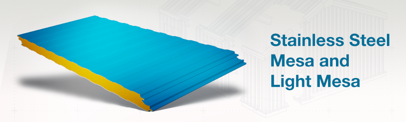
The Metl-Span CF Stainless wall panel has a highly reflective surface and the same attractive profile as the Metl-Span CF Mesa wall panel. The panel is suggested for use in areas where the faces are exposed to high-pressure wash-down and chemical cleaners. Note: Use of chlorides for cleaning may cause corrosion of stainless steel surfaces if not thoroughly rinsed off.
A double tongue-and-groove offset side joint permits concealed fastening.
Consistent insulating values are achieved with built-in thermal breaks, saving energy.
The metal and foam composite construction creates a rigid panel far stronger than the individual parts. This increases the span capability of the panels and reduces the need for secondary structural steel components.
Uses and Applications
In new and retrofit construction, Mesa panels function as walls, ceilings and roofing for cooler, freezer and food processing buildings. They are ideally suited for:
Cold Storage
| CF-42 MESA WALL PANEL ALLOWABLE CONNECTION LOAD (PSF) | |||||||||||||
| PANEL THICKNESS |
SPAN CONDITION |
FASTENING PATTERN |
PANEL SPAN (FT) | ||||||||||
| 5 | 6 | 7 | 8 | 9 | 10 | 11 | 12 | 13 | 14 | 15 | |||
| 2″ Thick | Two Spans |
Pattern FP1 | 31.6 | 25.8 | 21.7 | 18.8 | 16.5 | 14.8 | 13.3 | 12.2 | 11.2 | 10.3 | 9.6 |
| Pattern FP2 | 46.2 | 37.7 | 31.8 | 27.5 | 24.2 | 21.6 | 19.5 | 17.8 | 16.4 | 14.3 | 12.5 | ||
| Pattern FP3 | 58.3 | 47.6 | 40.2 | 34.7 | 30.5 | 26.0 | 22.1 | 19.0 | 16.4 | 14.3 | 12.5 | ||
| Three Or More Spans |
Pattern FP1 | 33.1 | 27.4 | 23.4 | 20.4 | 18.1 | 16.2 | 14.7 | 13.5 | 12.4 | 11.5 | 10.8 | |
| Pattern FP2 | 48.4 | 40.1 | 34.2 | 29.8 | 26.4 | 23.7 | 21.2 | 18.0 | 15.4 | 13.2 | 11.4 | ||
| Pattern FP3 | 61.1 | 50.6 | 43.2 | 36.5 | 30.2 | 25.2 | 21.2 | 18.0 | 15.4 | 13.2 | 11.4 | ||
| 2.5″ Thick | Two Spans |
Pattern FP1 | 33.3 | 27.2 | 22.9 | 19.8 | 17.4 | 15.5 | 14.0 | 12.7 | 11.7 | 10.8 | 10.1 |
| Pattern FP2 | 47.5 | 38.8 | 32.7 | 28.2 | 24.8 | 22.1 | 19.9 | 18.2 | 16.7 | 15.4 | 14.3 | ||
| Pattern FP3 | 60.1 | 49.0 | 41.3 | 35.7 | 31.4 | 28.0 | 25.2 | 23.0 | 21.1 | 19.5 | 17.3 | ||
| Three Or More Span |
Pattern FP1 | 34.6 | 28.6 | 24.4 | 21.3 | 18.8 | 16.9 | 15.3 | 14.0 | 12.9 | 12.0 | 11.2 | |
| Pattern FP2 | 49.3 | 40.8 | 34.8 | 30.3 | 26.8 | 24.1 | 21.9 | 20.0 | 18.4 | 17.1 | 16.0 | ||
| Pattern FP3 | 62.4 | 51.6 | 44.0 | 38.3 | 33.9 | 30.5 | 27.7 | 24.7 | 21.3 | 18.5 | 16.2 | ||
| 3″ Thick | Two Spans |
Pattern FP1 | 35.1 | 28.7 | 24.1 | 20.8 | 18.3 | 16.3 | 14.7 | 13.4 | 12.2 | 11.3 | 10.5 |
| Pattern FP2 | 48.8 | 39.8 | 33.6 | 28.9 | 25.4 | 22.6 | 20.4 | 18.6 | 17.0 | 15.7 | 14.6 | ||
| Pattern FP3 | 61.8 | 50.5 | 42.5 | 36.7 | 32.2 | 28.7 | 25.9 | 23.5 | 21.6 | 20.0 | 18.6 | ||
| Pattern FP4 | 71.1 | 58.0 | 48.9 | 42.2 | 37.0 | 33.0 | 29.7 | 27.1 | 24.8 | 22.9 | 21.3 | ||
| Three Or More Spans |
Pattern FP1 | 36.1 | 29.9 | 25.4 | 22.2 | 19.6 | 17.6 | 16.0 | 14.6 | 13.5 | 12.5 | 11.6 | |
| Pattern FP2 | 50.2 | 41.5 | 35.4 | 30.8 | 27.3 | 24.5 | 22.2 | 20.3 | 18.7 | 17.4 | 16.2 | ||
| Pattern FP3 | 63.7 | 52.6 | 44.8 | 39.0 | 34.6 | 31.0 | 28.2 | 25.8 | 23.7 | 22.0 | 20.5 | ||
| Pattern FP4 | 73.2 | 60.5 | 51.5 | 44.9 | 39.7 | 35.7 | 32.4 | 29.6 | 27.2 | 23.8 | 21.0 | ||
| 4″ Thick | Two Spans |
Pattern FP1 | 43.0 | 35.3 | 29.8 | 25.6 | 22.5 | 20.0 | 18.0 | 16.4 | 15.0 | 13.8 | 12.8 |
| Pattern FP2 | 63.0 | 51.8 | 43.6 | 37.6 | 33.0 | 29.3 | 26.4 | 24.0 | 22.0 | 20.3 | 18.8 | ||
| Pattern FP3 | 74.3 | 61.0 | 51.5 | 44.3 | 38.9 | 34.6 | 31.2 | 28.3 | 26.0 | 23.9 | 22.2 | ||
| Pattern FP4 | 79.6 | 65.4 | 55.1 | 47.5 | 41.7 | 37.1 | 33.4 | 30.3 | 27.8 | 25.7 | 23.8 | ||
| Pattern FP5 | 83.3 | 68.4 | 57.7 | 49.7 | 43.6 | 38.8 | 34.9 | 31.7 | 29.1 | 26.8 | 24.9 | ||
| Pattern FP9 | 89.5 | 73.5 | 62.0 | 53.4 | 46.9 | 41.7 | 37.5 | 34.1 | 31.3 | 28.8 | 26.8 | ||
| Pattern FP10 | 93.6 | 76.9 | 64.8 | 55.9 | 49.0 | 43.6 | 39.3 | 35.7 | 32.7 | 30.2 | 28.0 | ||
| Three Or More Spans |
Pattern FP1 | 44.0 | 36.3 | 30.9 | 26.9 | 23.8 | 21.3 | 19.3 | 17.7 | 16.3 | 15.1 | 14.1 | |
| Pattern FP2 | 64.4 | 53.2 | 45.3 | 39.4 | 34.9 | 31.3 | 28.3 | 25.9 | 23.9 | 22.1 | 20.6 | ||
| Pattern FP3 | 76.0 | 62.8 | 53.4 | 46.5 | 41.1 | 36.9 | 33.4 | 30.6 | 28.2 | 26.1 | 24.3 | ||
| Pattern FP4 | 81.4 | 67.2 | 57.2 | 49.8 | 44.1 | 39.5 | 35.8 | 32.8 | 30.2 | 28.0 | 26.1 | ||
| Pattern FP5 | 85.1 | 70.3 | 59.9 | 52.1 | 46.1 | 41.3 | 37.5 | 34.3 | 31.6 | 29.3 | 27.3 | ||
| Pattern FP9 | 91.5 | 75.6 | 64.2 | 55.6 | 49.0 | 43.8 | 39.6 | 36.2 | 33.3 | 30.8 | 28.7 | ||
| Pattern FP10 | 92.6 | 75.9 | 64.2 | 55.6 | 49.0 | 43.8 | 39.6 | 36.2 | 33.3 | 30.8 | 28.7 | ||
| 5″ Thick | Two Spans |
Pattern FP1 | 42.3 | 35.8 | 30.3 | 26.2 | 23.0 | 20.4 | 18.4 | 16.7 | 15.3 | 14.1 | 13.0 |
| Pattern FP2 | 61.9 | 52.5 | 44.5 | 38.4 | 33.6 | 29.9 | 26.9 | 24.4 | 22.4 | 20.6 | 19.1 | ||
| Pattern FP3 | 73.1 | 62.0 | 52.5 | 45.2 | 39.7 | 35.3 | 31.7 | 28.8 | 26.4 | 24.3 | 22.6 | ||
| Pattern FP4 | 78.2 | 66.4 | 56.2 | 48.5 | 42.5 | 37.8 | 34.0 | 30.9 | 28.3 | 26.1 | 24.2 | ||
| Pattern FP5 | 81.9 | 69.4 | 58.8 | 50.7 | 44.5 | 39.6 | 35.6 | 32.3 | 29.6 | 27.3 | 25.3 | ||
| Pattern FP9 | 88.0 | 74.6 | 63.2 | 54.5 | 47.8 | 42.5 | 38.2 | 34.7 | 31.8 | 29.3 | 27.2 | ||
| Pattern FP10 | 92.0 | 78.1 | 66.1 | 57.0 | 50.0 | 44.5 | 40.0 | 36.3 | 33.3 | 30.7 | 28.4 | ||
| Three Or More Spans |
Pattern FP1 | 43.5 | 36.6 | 31.2 | 27.1 | 24.0 | 21.5 | 19.4 | 17.8 | 16.4 | 15.2 | 14.1 | |
| Pattern FP2 | 63.8 | 53.7 | 45.7 | 39.7 | 35.1 | 31.5 | 28.5 | 26.1 | 24.0 | 22.2 | 20.7 | ||
| Pattern FP3 | 75.2 | 63.3 | 53.9 | 46.8 | 41.4 | 37.1 | 33.6 | 30.7 | 28.3 | 26.2 | 24.4 | ||
| Pattern FP4 | 80.6 | 67.8 | 57.7 | 50.2 | 44.4 | 39.8 | 36.0 | 32.9 | 30.3 | 28.1 | 26.2 | ||
| Pattern FP5 | 84.3 | 70.9 | 60.4 | 52.5 | 46.4 | 41.6 | 37.7 | 34.4 | 31.7 | 29.4 | 27.4 | ||
| Pattern FP9 | 90.6 | 76.2 | 64.9 | 56.4 | 49.9 | 44.7 | 40.5 | 37.0 | 34.1 | 31.6 | 29.4 | ||
| Pattern FP10 | 94.8 | 79.8 | 67.9 | 59.0 | 52.2 | 46.8 | 42.4 | 38.7 | 35.7 | 33.0 | 30.8 | ||
| 6″ Thick | Two Spans |
Pattern FP1 | 41.7 | 35.3 | 30.7 | 26.6 | 23.4 | 20.8 | 18.7 | 17.0 | 15.5 | 14.3 | 13.2 |
| Pattern FP2 | 61.2 | 51.7 | 45.0 | 39.0 | 34.3 | 30.5 | 27.4 | 24.9 | 22.8 | 21.0 | 19.4 | ||
| Pattern FP3 | 72.1 | 61.0 | 53.0 | 46.0 | 40.4 | 36.0 | 32.3 | 29.4 | 26.9 | 24.7 | 22.9 | ||
| Pattern FP4 | 77.2 | 65.3 | 56.8 | 49.3 | 43.3 | 38.5 | 34.6 | 31.4 | 28.8 | 26.5 | 24.5 | ||
| Pattern FP5 | 80.8 | 68.3 | 59.4 | 51.6 | 45.3 | 40.3 | 36.2 | 32.9 | 30.1 | 27.7 | 25.7 | ||
| Pattern FP9 | 86.9 | 73.4 | 63.9 | 55.5 | 48.7 | 43.3 | 39.0 | 35.4 | 32.3 | 29.8 | 27.6 | ||
| Pattern FP10 | 90.9 | 76.8 | 66.8 | 58.0 | 50.9 | 45.3 | 40.7 | 37.0 | 33.8 | 31.2 | 28.9 | ||
| Three Or More Spans |
Pattern FP1 | 42.8 | 36.3 | 31.4 | 27.3 | 24.1 | 21.6 | 19.6 | 17.9 | 16.4 | 15.2 | 14.2 | |
| Pattern FP2 | 62.7 | 53.2 | 46.0 | 40.0 | 35.4 | 31.7 | 28.7 | 26.2 | 24.1 | 22.3 | 20.8 | ||
| Pattern FP3 | 74.0 | 62.8 | 54.3 | 47.2 | 41.7 | 37.4 | 33.8 | 30.9 | 28.4 | 26.3 | 24.5 | ||
| Pattern FP4 | 79.3 | 67.2 | 58.1 | 50.5 | 44.7 | 40.0 | 36.2 | 33.1 | 30.5 | 28.2 | 26.3 | ||
| Pattern FP5 | 82.9 | 70.3 | 60.8 | 52.9 | 46.7 | 41.9 | 37.9 | 34.6 | 31.9 | 29.5 | 27.5 | ||
| Pattern FP9 | 89.1 | 75.6 | 65.4 | 56.8 | 50.2 | 45.0 | 40.8 | 37.2 | 34.3 | 31.7 | 29.6 | ||
| Pattern FP10 | 93.2 | 79.1 | 68.4 | 59.5 | 52.6 | 47.1 | 42.6 | 38.9 | 35.8 | 33.2 | 30.9 | ||
| CF-36 MESA WALL PANEL ALLOWABLE CONNECTION LOAD (PSF) | ||||||||||
| PANEL THICKENSS |
SPAN CONDITION |
FASTENING PATTERN |
PANEL SPAN (FT) | |||||||
| 5 | 6 | 7 | 8 | 9 | 10 | 11 | 12 | |||
| 2″ Thick | Two Spans | Pattern FP1 | 40.5 | 34.6 | 30.3 | 26.8 | 23.6 | 21.0 | 19.0 | 17.3 |
| 2.5″ Thick | Pattern FP1 | 45.0 | 38.5 | 33.7 | 30.1 | 27.1 | 24.1 | 21.8 | 19.8 | |
| 3″ Thick | Pattern FP1 | 49.0 | 41.8 | 36.6 | 32.7 | 29.5 | 26.9 | 24.3 | 22.2 | |
| 2″ Thick | Three Or More Spans |
Pattern FP1 | 41.4 | 35.1 | 30.4 | 26.8 | 24.0 | 21.7 | 19.8 | 18.2 |
| 2.5″ Thick | Pattern FP1 | 46.3 | 39.3 | 34.1 | 30.2 | 27.0 | 24.4 | 22.3 | 20.5 | |
| 3″ Thick | Pattern FP1 | 50.5 | 42.9 | 37.3 | 33.1 | 29.6 | 26.9 | 24.6 | 22.6 | |
| CF-30 MESA WALL PANEL ALLOWABLE CONNECTION LOAD (PSF) | ||||||||||
| PANEL THICKENSS |
SPAN CONDITION |
FASTENING PATTERN |
PANEL SPAN (FT) | |||||||
| 5 | 6 | 7 | 8 | 9 | 10 | 11 | 12 | |||
| 2″ Thick | Two Spans | Pattern FP1 | 48.6 | 41.6 | 36.4 | 32.1 | 28.3 | 25.2 | 21.2 | 17.3 |
| 2.5″ Thick | Pattern FP1 | 54.1 | 46.2 | 40.5 | 36.1 | 32.5 | 29.0 | 26.1 | 21.5 | |
| 3″ Thick | Pattern FP1 | 58.8 | 50.2 | 44.0 | 39.2 | 35.4 | 32.3 | 29.2 | 25.5 | |
| 2″ Thick | Three Or More Spans |
Pattern FP1 | 49.7 | 42.1 | 36.5 | 32.2 | 28.8 | 26.0 | 22.0 | 18.7 |
| 2.5″ Thick | Pattern FP1 | 55.6 | 47.1 | 41.0 | 36.2 | 32.4 | 29.3 | 26.8 | 23.7 | |
| 3″ Thick | Pattern FP1 | 60.6 | 51.5 | 44.8 | 39.7 | 35.6 | 32.2 | 29.5 | 27.1 | |
| CF MESA WALL PANEL ALLOWABLE POSITIVE LOAD (PSF) | |||||||||||||
| PANEL THICKNESS |
SPAN CONDITION |
DESIGN CRITERIA |
PANEL SPAN (FT) | ||||||||||
| 5 | 6 | 7 | 8 | 9 | 10 | 11 | 12 | 13 | 14 | 15 | |||
| 2″ Thick | Two Spans |
Bending & Shear | 68.7 | 56.1 | 47.3 | 40.9 | 36.0 | 32.1 | 29.0 | 26.5 | 22.2 | 18.8 | 16.1 |
| Deflection (L/180) | 70.0 | 55.1 | 44.6 | 36.7 | 30.7 | 26.0 | 22.1 | 19.0 | 16.4 | 14.3 | 12.5 | ||
| Three Or More Spans |
Bending & Shear | 67.5 | 55.6 | 47.2 | 41.1 | 36.4 | 32.6 | 29.6 | 27.0 | 24.9 | 21.9 | 18.9 | |
| Deflection (L/180) | 70.8 | 55.6 | 44.6 | 36.5 | 30.2 | 25.2 | 21.2 | 18.0 | 15.4 | 13.2 | 11.4 | ||
| 2.5″ Thick | Two Spans | Bending & Shear | 79.3 | 64.8 | 54.6 | 47.1 | 41.4 | 36.9 | 33.3 | 30.4 | 27.1 | 22.8 | 19.4 |
| Deflection (L/180) | 87.9 | 69.9 | 57.0 | 47.5 | 40.1 | 34.2 | 29.5 | 25.6 | 22.3 | 19.6 | 17.3 | ||
| Three Or More Spans |
Bending & Shear | 77.6 | 63.8 | 54.1 | 47.0 | 41.6 | 37.2 | 33.7 | 30.9 | 28.4 | 25.9 | 22.4 | |
| Deflection (L/180) | 88.9 | 70.6 | 57.5 | 47.6 | 39.9 | 33.7 | 28.8 | 24.7 | 21.3 | 18.5 | 16.2 | ||
| 3″ Thick | Two Spans | Bending & Shear | 89.0 | 72.7 | 61.2 | 52.8 | 46.4 | 41.3 | 37.2 | 33.9 | 31.1 | 26.7 | 22.7 |
| Deflection (L/180) | 104.1 | 83.3 | 68.4 | 57.3 | 48.8 | 41.9 | 36.4 | 31.8 | 28.0 | 24.8 | 22.0 | ||
| Three Or More Spans |
Bending & Shear | 86.9 | 71.3 | 60.4 | 52.4 | 46.3 | 41.4 | 37.5 | 34.3 | 31.6 | 29.2 | 25.6 | |
| Deflection (L/180) | 105.2 | 84.3 | 69.2 | 57.8 | 48.9 | 41.8 | 36.0 | 31.2 | 27.2 | 23.8 | 21.0 | ||
| 4″ Thick | Two Spans | Bending & Shear | 95.1 | 77.8 | 65.6 | 56.5 | 49.6 | 44.1 | 39.7 | 36.1 | 33.1 | 30.5 | 28.3 |
| Deflection (L/180) | 130.8 | 105.6 | 87.6 | 74.1 | 63.6 | 55.2 | 48.4 | 42.8 | 38.1 | 34.0 | 30.6 | ||
| Three Or More Spans |
Bending & Shear | 92.6 | 75.9 | 64.2 | 55.6 | 49.0 | 43.8 | 39.6 | 36.2 | 33.3 | 30.8 | 28.7 | |
| Deflection (L/180) | 131.7 | 106.6 | 88.6 | 74.9 | 64.2 | 55.6 | 48.6 | 42.7 | 37.8 | 33.5 | 29.9 | ||
| 5″ Thick | Two Spans | Bending & Shear | 108.8 | 89.3 | 75.4 | 65.0 | 57.0 | 50.7 | 45.6 | 41.4 | 37.9 | 35.0 | 32.4 |
| Deflection (L/180) | 149.1 | 121.2 | 101.2 | 86.2 | 74.5 | 65.1 | 57.5 | 51.2 | 45.8 | 41.3 | 37.4 | ||
| Three Or More Spans |
Bending & Shear | 106.1 | 87.0 | 73.5 | 63.6 | 56.0 | 50.0 | 45.1 | 41.2 | 37.8 | 35.0 | 32.5 | |
| Deflection (L/180) | 149.9 | 122.1 | 102.2 | 87.1 | 75.3 | 65.9 | 58.1 | 51.5 | 46.0 | 41.3 | 37.2 | ||
| 6″ Thick | Two Spans | Bending & Shear | 121.2 | 99.7 | 84.3 | 72.8 | 63.9 | 56.9 | 51.2 | 46.4 | 42.5 | 39.1 | 36.3 |
| Deflection (L/180) | 159.0 | 129.9 | 109.1 | 93.3 | 81.1 | 71.3 | 63.3 | 56.6 | 51.0 | 46.1 | 42.0 | ||
| Three Or More Spans |
Bending & Shear | 118.5 | 97.2 | 82.1 | 71.0 | 62.5 | 55.7 | 50.3 | 45.8 | 42.0 | 38.9 | 36.1 | |
| Deflection (L/180) | 159.5 | 130.6 | 109.8 | 94.2 | 81.9 | 72.1 | 64.0 | 57.2 | 51.4 | 46.5 | 42.2 | ||
| CF-42 LIGHT MESA WALL PANEL ALLOWABLE CONNECTION LOAD (PSF) | |||||||||||||
| PANEL THICKNESS |
SPAN CONDITION |
FASTENING PATTERN |
PANEL SPAN (FT) | ||||||||||
| 5 | 6 | 7 | 8 | 9 | 10 | 11 | 12 | 13 | 14 | 15 | |||
| 2″ Thick | Two Spans | Pattern FP1 | 31.6 | 25.8 | 21.7 | 18.8 | 16.5 | 14.8 | 13.3 | 12.2 | 11.2 | 10.3 | 9.6 |
| Pattern FP2 | 46.2 | 37.7 | 31.8 | 27.5 | 24.2 | 21.6 | 19.5 | 17.8 | 16.4 | 14.3 | 12.5 | ||
| Pattern FP3 | 58.3 | 47.6 | 40.2 | 34.7 | 30.5 | 26.0 | 22.1 | 19.0 | 16.4 | 14.3 | 12.5 | ||
| Three Or More Spans |
Pattern FP1 | 33.1 | 27.4 | 23.4 | 20.4 | 18.1 | 16.2 | 14.7 | 13.5 | 12.4 | 11.5 | 10.8 | |
| Pattern FP2 | 48.4 | 40.1 | 34.2 | 29.8 | 26.4 | 23.7 | 21.2 | 18.0 | 15.4 | 13.2 | 11.4 | ||
| Pattern FP3 | 61.1 | 50.6 | 43.2 | 36.5 | 30.2 | 25.2 | 21.2 | 18.0 | 15.4 | 13.2 | 11.4 | ||
| 2.5″ Thick | Two Spans | Pattern FP1 | 33.3 | 27.2 | 22.9 | 19.8 | 17.4 | 15.5 | 14.0 | 12.7 | 11.7 | 10.8 | 10.1 |
| Pattern FP2 | 47.5 | 38.8 | 32.7 | 28.2 | 24.8 | 22.1 | 19.9 | 18.2 | 16.7 | 15.4 | 14.3 | ||
| Pattern FP3 | 60.1 | 49.0 | 41.3 | 35.7 | 31.4 | 28.0 | 25.2 | 23.0 | 21.1 | 19.5 | 17.3 | ||
| Three Or More Spans |
Pattern FP1 | 34.6 | 28.6 | 24.4 | 21.3 | 18.8 | 16.9 | 15.3 | 14.0 | 12.9 | 12.0 | 11.2 | |
| Pattern FP2 | 49.3 | 40.8 | 34.8 | 30.3 | 26.8 | 24.1 | 21.9 | 20.0 | 18.4 | 17.1 | 16.0 | ||
| Pattern FP3 | 62.4 | 51.6 | 44.0 | 38.3 | 33.9 | 30.5 | 27.7 | 24.7 | 21.3 | 18.5 | 16.2 | ||
| 3″ Thick | Two Spans | Pattern FP1 | 35.1 | 28.7 | 24.1 | 20.8 | 18.3 | 16.3 | 14.7 | 13.4 | 12.2 | 11.3 | 10.5 |
| Pattern FP2 | 48.8 | 39.8 | 33.6 | 28.9 | 25.4 | 22.6 | 20.4 | 18.6 | 17.0 | 15.7 | 14.6 | ||
| Pattern FP3 | 61.8 | 50.5 | 42.5 | 36.7 | 32.2 | 28.7 | 25.9 | 23.5 | 21.6 | 20.0 | 18.6 | ||
| Pattern FP4 | 71.1 | 58.0 | 48.9 | 42.2 | 37.0 | 33.0 | 29.7 | 27.1 | 24.8 | 22.9 | 21.3 | ||
| Three Or More Spans |
Pattern FP1 | 36.1 | 29.9 | 25.4 | 22.2 | 19.6 | 17.6 | 16.0 | 14.6 | 13.5 | 12.5 | 11.6 | |
| Pattern FP2 | 50.2 | 41.5 | 35.4 | 30.8 | 27.3 | 24.5 | 22.2 | 20.3 | 18.7 | 17.4 | 16.2 | ||
| Pattern FP3 | 63.7 | 52.6 | 44.8 | 39.0 | 34.6 | 31.0 | 28.2 | 25.8 | 23.7 | 22.0 | 20.5 | ||
| Pattern FP4 | 73.2 | 60.5 | 51.5 | 44.9 | 39.7 | 35.7 | 32.4 | 29.6 | 27.2 | 23.8 | 21.0 | ||
| 4″ Thick | Two Spans | Pattern FP1 | 43.0 | 35.3 | 29.8 | 25.6 | 22.5 | 20.0 | 18.0 | 16.4 | 15.0 | 13.8 | 12.8 |
| Pattern FP2 | 63.0 | 51.8 | 43.6 | 37.6 | 33.0 | 29.3 | 26.4 | 24.0 | 22.0 | 20.3 | 18.8 | ||
| Pattern FP3 | 74.3 | 61.0 | 51.5 | 44.3 | 38.9 | 34.6 | 31.2 | 28.3 | 26.0 | 23.9 | 22.2 | ||
| Pattern FP4 | 79.6 | 65.4 | 55.1 | 47.5 | 41.7 | 37.1 | 33.4 | 30.3 | 27.8 | 25.7 | 23.8 | ||
| Pattern FP5 | 83.3 | 68.4 | 57.7 | 49.7 | 43.6 | 38.8 | 34.9 | 31.7 | 29.1 | 26.8 | 24.9 | ||
| Pattern FP9 | 89.5 | 73.5 | 62.0 | 53.4 | 46.9 | 41.7 | 37.5 | 34.1 | 31.3 | 28.8 | 26.8 | ||
| Pattern FP10 | 93.6 | 76.9 | 64.8 | 55.9 | 49.0 | 43.6 | 39.3 | 35.7 | 32.7 | 30.2 | 28.0 | ||
| Three Or More Spans |
Pattern FP1 | 44.0 | 36.3 | 30.9 | 26.9 | 23.8 | 21.3 | 19.3 | 17.7 | 16.3 | 15.1 | 14.1 | |
| Pattern FP2 | 64.4 | 53.2 | 45.3 | 39.4 | 34.9 | 31.3 | 28.3 | 25.9 | 23.9 | 22.1 | 20.6 | ||
| Pattern FP3 | 76.0 | 62.8 | 53.4 | 46.5 | 41.1 | 36.9 | 33.4 | 30.6 | 28.2 | 26.1 | 24.3 | ||
| Pattern FP4 | 81.4 | 67.2 | 57.2 | 49.8 | 44.1 | 39.5 | 35.8 | 32.8 | 30.2 | 28.0 | 26.1 | ||
| Pattern FP5 | 85.1 | 70.3 | 59.9 | 52.1 | 46.1 | 41.3 | 37.5 | 34.3 | 31.6 | 29.3 | 27.3 | ||
| Pattern FP9 | 91.5 | 75.6 | 64.2 | 55.6 | 49.0 | 43.8 | 39.6 | 36.2 | 33.3 | 30.8 | 28.7 | ||
| Pattern FP10 | 92.6 | 75.9 | 64.2 | 55.6 | 49.0 | 43.8 | 39.6 | 36.2 | 33.3 | 30.8 | 28.7 | ||
| 5″ Thick | Two Spans | Pattern FP1 | 42.3 | 35.8 | 30.3 | 26.2 | 23.0 | 20.4 | 18.4 | 16.7 | 15.3 | 14.1 | 13.0 |
| Pattern FP2 | 61.9 | 52.5 | 44.5 | 38.4 | 33.6 | 29.9 | 26.9 | 24.4 | 22.4 | 20.6 | 19.1 | ||
| Pattern FP3 | 73.1 | 62.0 | 52.5 | 45.2 | 39.7 | 35.3 | 31.7 | 28.8 | 26.4 | 24.3 | 22.6 | ||
| Pattern FP4 | 78.2 | 66.4 | 56.2 | 48.5 | 42.5 | 37.8 | 34.0 | 30.9 | 28.3 | 26.1 | 24.2 | ||
| Pattern FP5 | 81.9 | 69.4 | 58.8 | 50.7 | 44.5 | 39.6 | 35.6 | 32.3 | 29.6 | 27.3 | 25.3 | ||
| Pattern FP9 | 88.0 | 74.6 | 63.2 | 54.5 | 47.8 | 42.5 | 38.2 | 34.7 | 31.8 | 29.3 | 27.2 | ||
| Pattern FP10 | 92.0 | 78.1 | 66.1 | 57.0 | 50.0 | 44.5 | 40.0 | 36.3 | 33.3 | 30.7 | 28.4 | ||
| Three Or More Spans |
Pattern FP1 | 43.5 | 36.6 | 31.2 | 27.1 | 24.0 | 21.5 | 19.4 | 17.8 | 16.4 | 15.2 | 14.1 | |
| Pattern FP2 | 63.8 | 53.7 | 45.7 | 39.7 | 35.1 | 31.5 | 28.5 | 26.1 | 24.0 | 22.2 | 20.7 | ||
| Pattern FP3 | 75.2 | 63.3 | 53.9 | 46.8 | 41.4 | 37.1 | 33.6 | 30.7 | 28.3 | 26.2 | 24.4 | ||
| Pattern FP4 | 80.6 | 67.8 | 57.7 | 50.2 | 44.4 | 39.8 | 36.0 | 32.9 | 30.3 | 28.1 | 26.2 | ||
| Pattern FP5 | 84.3 | 70.9 | 60.4 | 52.5 | 46.4 | 41.6 | 37.7 | 34.4 | 31.7 | 29.4 | 27.4 | ||
| Pattern FP9 | 90.6 | 76.2 | 64.9 | 56.4 | 49.9 | 44.7 | 40.5 | 37.0 | 34.1 | 31.6 | 29.4 | ||
| Pattern FP10 | 94.8 | 79.8 | 67.9 | 59.0 | 52.2 | 46.8 | 42.4 | 38.7 | 35.7 | 33.0 | 30.8 | ||
| 6″ Thick | Two Spans | Pattern FP1 | 41.7 | 35.3 | 30.7 | 26.6 | 23.4 | 20.8 | 18.7 | 17.0 | 15.5 | 14.3 | 13.2 |
| Pattern FP2 | 61.2 | 51.7 | 45.0 | 39.0 | 34.3 | 30.5 | 27.4 | 24.9 | 22.8 | 21.0 | 19.4 | ||
| Pattern FP3 | 72.1 | 61.0 | 53.0 | 46.0 | 40.4 | 36.0 | 32.3 | 29.4 | 26.9 | 24.7 | 22.9 | ||
| Pattern FP4 | 77.2 | 65.3 | 56.8 | 49.3 | 43.3 | 38.5 | 34.6 | 31.4 | 28.8 | 26.5 | 24.5 | ||
| Pattern FP5 | 80.8 | 68.3 | 59.4 | 51.6 | 45.3 | 40.3 | 36.2 | 32.9 | 30.1 | 27.7 | 25.7 | ||
| Pattern FP9 | 86.9 | 73.4 | 63.9 | 55.5 | 48.7 | 43.3 | 39.0 | 35.4 | 32.3 | 29.8 | 27.6 | ||
| Pattern FP10 | 90.9 | 76.8 | 66.8 | 58.0 | 50.9 | 45.3 | 40.7 | 37.0 | 33.8 | 31.2 | 28.9 | ||
| Three Or More Spans |
Pattern FP1 | 42.8 | 36.3 | 31.4 | 27.3 | 24.1 | 21.6 | 19.6 | 17.9 | 16.4 | 15.2 | 14.2 | |
| Pattern FP2 | 62.7 | 53.2 | 46.0 | 40.0 | 35.4 | 31.7 | 28.7 | 26.2 | 24.1 | 22.3 | 20.8 | ||
| Pattern FP3 | 74.0 | 62.8 | 54.3 | 47.2 | 41.7 | 37.4 | 33.8 | 30.9 | 28.4 | 26.3 | 24.5 | ||
| Pattern FP4 | 79.3 | 67.2 | 58.1 | 50.5 | 44.7 | 40.0 | 36.2 | 33.1 | 30.5 | 28.2 | 26.3 | ||
| Pattern FP5 | 82.9 | 70.3 | 60.8 | 52.9 | 46.7 | 41.9 | 37.9 | 34.6 | 31.9 | 29.5 | 27.5 | ||
| Pattern FP9 | 89.1 | 75.6 | 65.4 | 56.8 | 50.2 | 45.0 | 40.8 | 37.2 | 34.3 | 31.7 | 29.6 | ||
| Pattern FP10 | 93.2 | 79.1 | 68.4 | 59.5 | 52.6 | 47.1 | 42.6 | 38.9 | 35.8 | 33.2 | 30.9 | ||
| CF-36 LIGHT MESA WALL PANEL ALLOWABLE CONNECTION LOAD (PSF) | ||||||||||
| PANEL THICKNESS |
SPAN CONDITION |
FASTENING PATTERN |
PANEL SPAN (FT) | |||||||
| 5 | 6 | 7 | 8 | 9 | 10 | 11 | 12 | |||
| 2″ Thick | Two Spans | Pattern FP1 | 40.5 | 34.6 | 30.3 | 26.8 | 23.6 | 21.0 | 19.0 | 17.3 |
| 2.5″ Thick | Pattern FP1 | 45.0 | 38.5 | 33.7 | 30.1 | 27.1 | 24.1 | 21.8 | 19.8 | |
| 3″ Thick | Pattern FP1 | 49.0 | 41.8 | 36.6 | 32.7 | 29.5 | 26.9 | 24.3 | 22.2 | |
| 2″ Thick | Three Or More Spans |
Pattern FP1 | 41.4 | 35.1 | 30.4 | 26.8 | 24.0 | 21.7 | 19.8 | 18.2 |
| 2.5″ Thick | Pattern FP1 | 46.3 | 39.3 | 34.1 | 30.2 | 27.0 | 24.4 | 22.3 | 20.5 | |
| 3″ Thick | Pattern FP1 | 50.5 | 42.9 | 37.3 | 33.1 | 29.6 | 26.9 | 24.6 | 22.6 | |
| CF-30 LIGHT MESA WALL PANEL ALLOWABLE CONNECTION LOAD (PSF) | ||||||||||
| PANEL THICKNESS |
SPAN CONDITION |
FASTENING PATTERN |
PANEL SPAN (FT) | |||||||
| 5 | 6 | 7 | 8 | 9 | 10 | 11 | 12 | |||
| 2″ Thick | Two Spans | Pattern FP1 | 48.6 | 41.6 | 36.4 | 32.1 | 28.3 | 25.2 | 21.2 | 17.3 |
| 2.5″ Thick | Pattern FP1 | 54.1 | 46.2 | 40.5 | 36.1 | 32.5 | 29.0 | 26.1 | 21.5 | |
| 3″ Thick | Pattern FP1 | 58.8 | 50.2 | 44.0 | 39.2 | 35.4 | 32.3 | 29.2 | 25.5 | |
| 2″ Thick | Three Or More Spans |
Pattern FP1 | 49.7 | 42.1 | 36.5 | 32.2 | 28.8 | 26.0 | 22.0 | 18.7 |
| 2.5″ Thick | Pattern FP1 | 55.6 | 47.1 | 41.0 | 36.2 | 32.4 | 29.3 | 26.8 | 23.7 | |
| 3″ Thick | Pattern FP1 | 60.6 | 51.5 | 44.8 | 39.7 | 35.6 | 32.2 | 29.5 | 27.1 | |
| CF LIGHT MESA WALL PANEL ALLOWABLE POSITIVE LOAD (PSF) | |||||||||||||
| PANEL THICKNESS |
SPAN CONDITION |
DESIGN CRITERIA |
PANEL SPAN (FT) | ||||||||||
| 5 | 6 | 7 | 8 | 9 | 10 | 11 | 12 | 13 | 14 | 15 | |||
| 2″ Thick | Two Spans | Bending & Shear | 71.9 | 58.7 | 49.5 | 42.8 | 37.7 | 33.7 | 26.9 | 21.9 | 18.3 | 15.5 | 13.3 |
| Deflection (L/180) | 73.0 | 57.4 | 46.3 | 38.1 | 31.8 | 26.8 | 22.8 | 19.6 | 16.9 | 14.7 | 12.8 | ||
| Three Or More Spans |
Bending & Shear | 70.8 | 58.3 | 49.5 | 43.1 | 38.1 | 34.2 | 30.2 | 25.0 | 21.1 | 18.1 | 15.6 | |
| Deflection (L/180) | 73.8 | 57.8 | 46.3 | 37.7 | 31.1 | 25.9 | 21.8 | 18.5 | 15.7 | 13.5 | 11.6 | ||
| 2.5″ Thick | Two Spans | Bending & Shear | 82.2 | 67.2 | 56.6 | 48.9 | 43.0 | 38.3 | 34.5 | 27.9 | 23.1 | 19.5 | 16.7 |
| Deflection (L/180) | 90.9 | 72.2 | 58.9 | 48.9 | 41.3 | 35.2 | 30.3 | 26.3 | 22.9 | 20.1 | 17.7 | ||
| Three Or More Spans |
Bending & Shear | 80.6 | 66.2 | 56.2 | 48.8 | 43.2 | 38.7 | 35.0 | 31.0 | 26.1 | 22.3 | 19.2 | |
| Deflection (L/180) | 92.0 | 73.0 | 59.3 | 49.0 | 41.0 | 34.6 | 29.5 | 25.3 | 21.8 | 18.9 | 16.5 | ||
| 3″ Thick | Two Spans | Bending & Shear | 91.7 | 74.9 | 63.1 | 54.4 | 47.8 | 42.6 | 38.4 | 33.2 | 27.3 | 22.9 | 19.4 |
| Deflection (L/180) | 107.2 | 85.6 | 70.3 | 58.9 | 50.0 | 43.0 | 37.3 | 32.6 | 28.6 | 25.3 | 22.5 | ||
| Three Or More Spans |
Bending & Shear | 89.5 | 73.5 | 62.3 | 54.0 | 47.7 | 42.7 | 38.7 | 35.4 | 30.0 | 25.5 | 22.0 | |
| Deflection (L/180) | 108.3 | 86.6 | 71.0 | 59.3 | 50.1 | 42.8 | 36.8 | 31.9 | 27.7 | 24.3 | 21.3 | ||
| 4″ Thick | Two Spans | Bending & Shear | 97.3 | 79.6 | 67.1 | 57.8 | 50.7 | 45.1 | 40.6 | 36.9 | 33.9 | 31.2 | 29.0 |
| Deflection (L/180) | 133.6 | 107.9 | 89.4 | 75.6 | 64.9 | 56.3 | 49.4 | 43.6 | 38.8 | 34.6 | 31.1 | ||
| Three Or More Spans |
Bending & Shear | 94.7 | 77.6 | 65.7 | 56.9 | 50.2 | 44.8 | 40.6 | 37.0 | 34.1 | 31.5 | 29.4 | |
| Deflection (L/180) | 134.6 | 108.9 | 90.4 | 76.4 | 65.5 | 56.7 | 49.5 | 43.5 | 38.4 | 34.1 | 30.4 | ||
| 5″ Thick | Two Spans | Bending & Shear | 110.8 | 90.9 | 76.7 | 66.2 | 58.1 | 51.6 | 46.5 | 42.2 | 38.6 | 35.6 | 33.0 |
| Deflection (L/180) | 151.8 | 123.4 | 103.0 | 87.6 | 75.7 | 66.2 | 58.4 | 52.0 | 46.5 | 41.9 | 37.9 | ||
| Three Or More Spans |
Bending & Shear | 108.0 | 88.5 | 74.8 | 64.7 | 57.0 | 50.9 | 46.0 | 41.9 | 38.5 | 35.6 | 33.2 | |
| Deflection (L/180) | 152.5 | 124.3 | 103.9 | 88.6 | 76.6 | 66.9 | 59.0 | 52.3 | 46.7 | 41.9 | 37.7 | ||
| 6″ Thick | Two Spans | Bending & Shear | 123.1 | 101.2 | 85.6 | 73.9 | 64.9 | 57.7 | 51.9 | 47.1 | 43.1 | 39.7 | 36.8 |
| Deflection (L/180) | 161.3 | 131.8 | 110.6 | 94.7 | 82.2 | 72.3 | 64.1 | 57.3 | 51.6 | 46.7 | 42.5 | ||
| Three Or More Spans |
Bending & Shear | 120.2 | 98.6 | 83.4 | 72.1 | 63.4 | 56.6 | 51.0 | 46.5 | 42.7 | 39.4 | 36.7 | |
| Deflection (L/180) | 161.9 | 132.5 | 111.4 | 95.5 | 83.1 | 73.1 | 64.9 | 58.0 | 52.1 | 47.1 | 42.7 | ||
| WALL PANELS ALLOWABLE NEGATIVE LOAD (PSF) BASED ON SIDE JOINT CONNECTION ONLY | |||||||||||
| CF PANEL | THICKNESS | SPAN CONDITION | PANEL SPAN (FEET) | ||||||||
| 4.0 | 5.0 | 6.0 | 7.0 | 8.0 | 9.0 | 10.0 | 11.0 | 12.0 | |||
| 30″ WIDE | 2″ | TWO SPANS | 47.0 | 37.6 | 31.3 | 26.9 | 23.5 | 20.9 | 18.8 | 17.1 | 15.7 |
| 2.5″ | 53.8 | 43.1 | 35.9 | 30.8 | 26.9 | 23.9 | 21.5 | 19.6 | 17.9 | ||
| 3″ | 59.8 | 47.8 | 39.9 | 34.2 | 29.9 | 26.6 | 23.9 | 21.7 | 19.9 | ||
| 2″ | Three Or More Spans |
51.5 | 41.2 | 34.4 | 29.5 | 25.8 | 22.9 | 20.6 | 18.7 | 17.2 | |
| 2.5″ | 59.0 | 47.2 | 39.4 | 33.7 | 29.5 | 26.2 | 23.6 | 21.5 | 19.7 | ||
| 3″ | 65.5 | 52.4 | 43.7 | 37.5 | 32.8 | 29.1 | 26.2 | 23.8 | 21.8 | ||
| 36″ WIDE | 2″ | TWO SPANS | 39.2 | 31.3 | 26.1 | 22.4 | 19.6 | 17.4 | 15.7 | 14.2 | 13.1 |
| 2.5″ | 44.9 | 35.9 | 29.9 | 25.6 | 22.4 | 19.9 | 17.9 | 16.3 | 15.0 | ||
| 3″ | 49.8 | 39.8 | 33.2 | 28.5 | 24.9 | 22.1 | 19.9 | 18.1 | 16.6 | ||
| 2″ | Three Or More Spans |
43.0 | 34.4 | 28.6 | 24.5 | 21.5 | 19.1 | 17.2 | 15.6 | 14.3 | |
| 2.5″ | 49.2 | 39.4 | 32.8 | 28.1 | 24.6 | 21.9 | 19.7 | 17.9 | 16.4 | ||
| 3″ | 54.6 | 43.7 | 36.4 | 31.2 | 27.3 | 24.3 | 21.8 | 19.9 | 18.2 | ||
| Allowable Single Span for Inward and Outward Load of 10 psf | |||||
| Panel Type |
Thickness (in) |
Design Criteria | Allowable Span (ft) |
||
| Bending Stress |
Shear Stress |
Deflection Limit L/120 |
|||
| CF-42 Mesa/Mesa or CF-45 Mesa/Mesa |
2 | 18.1 | 38.5 | 15.8 | 15.8 |
| 2.5 | 19.5 | 43.8 | 18.6 | 18.6 | |
| 3 | 20.6 | 48.5 | 21.2 | 20.6 | |
| 4 | 24.7 | 50.8 | 26.0 | 24.7 | |
| 5 | 27.9 | 57.2 | 30.3 | 27.9 | |
| 6 | 30.1 | 63.3 | 34.0 | 30.1 | |
| ALLOWABLE SPAN IN FEET/METERS FOR PARTITION PANELS | ||||||||||||
| PARTITION PANELS THICKNESS – IN./CM. | ||||||||||||
| LOAD PSF/KPA DEFL. L/120 | 2 | 5.08 | 2.5 | 6.35 | 3 | 7.62 | 4 | 10.16 | 5 | 12.7 | 6 | 15.24 |
| 5/.24 | 20.80 | 6.34 | 24.50 | 7.47 | 27.90 | 8.50 | 34.10 | 10.39 | 39.50 | 12.04 | 45.60 | 12.98 |
| ALLOWABLE SPAN IN FEET/METERS FOR PARTITION PANELS | ||||||||||||
| PARTITION PANELS THICKNESS – IN./CM. | ||||||||||||
| LOAD PSF/KPA DEFL. L/120 |
2 | 5.08 | 2.5 | 6.35 | 3 | 7.62 | 4 | 10.16 | 5 | 12.7 | 6 | 15.24 |
| 5/.24 | 20.80 | 6.34 | 24.50 | 7.47 | 27.10 | 8.26 | 32.40 | 9.87 | 34.60 | 10.54 | 36.50 | 11.12 |