Contact Us: 800-387-5335
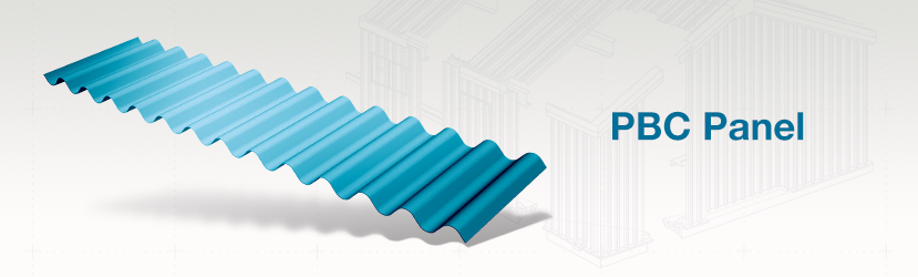
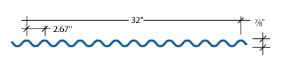
The PBC panels can be used for both roof and wall applications. PBC panels are attached to a building structure with exposed fasteners. The PBC panel is often used in horizontal applications on walls.
PBC – Section Properties
| NEGATIVE BENDING | POSITIVE BENDING | |||||||
| Panel Gauge | FY (KSI) | WEIGHT (PSF) | Ixe (IN.4/FT.) | Sxe (IN.3/FT.) | Maxo (KIP-IN.) | Ixe (IN.4/FT.) | Sxe (IN.3/FT.) | Maxo (KIP-IN.) |
| 29 | 60* | 0.84 | 0.0187 | 0.0405 | 1.4547 | 0.0187 | 0.0405 | 1.4547 |
| 26 | 60* | 1.06 | 0.0249 | 0.055 | 1.9759 | 0.0249 | 0.055 | 1.9759 |
| 24 | 50 | 1.28 | 0.0318 | 0.0711 | 2.1296 | 0.0318 | 0.0711 | 2.1296 |
| 22 | 50 | 1.62 | 0.0415 | 0.0905 | 2.7099 | 0.0415 | 0.0905 | 2.7099 |
*Fy is 60-ksi in accordance with the 2001 edition of the North American Specification For Design Of Cold-Formed Steel Structural Members – A2.3.2.
Allowable Uniform Loads In Pounds Per Square Foot
| 29 Gauge (Fy = 60 Ksi) | ||||||||
| SPAN TYPE | LOAD TYPE | SPAN IN FEET | ||||||
| 3.0 | 4.0 | 5.0 | 6.0 | 7.0 | 8.0 | 9.0 | ||
| SINGLE | NEGATIVE WIND LOAD | 107.8 | 60.6 | 38.8 | 26.9 | 19.8 | 15.2 | 12.0 |
| LIVE LOAD / DEFLECTION |
60.5 | 25.5 | 13.1 | 7.6 | 4.8 | 3.2 | 2.2 | |
| 2-SPAN | NEGATIVE WIND LOAD | 107.8 | 60.6 | 38.8 | 26.9 | 19.8 | 15.2 | 12.0 |
| LIVE LOAD / DEFLECTION |
94.3 | 56.0 | 31.5 | 18.2 | 11.5 | 7.7 | 5.4 | |
| 3-SPAN | NEGATIVE WIND LOAD | 134.7 | 75.8 | 48.5 | 33.7 | 24.7 | 18.9 | 15.0 |
| LIVE LOAD / DEFLECTION |
112.3 | 48.2 | 24.7 | 14.3 | 9.0 | 6.0 | 4.2 | |
| 4-SPAN | NEGATIVE WIND LOAD | 125.8 | 70.7 | 45.3 | 31.4 | 23.1 | 17.7 | 14.0 |
| LIVE LOAD / DEFLECTION |
106.6 | 51.2 | 26.2 | 15.2 | 9.5 | 6.4 | 4.5 | |
| 26 Gauge (Fy = 60 Ksi ) | ||||||||
| SPAN TYPE | LOAD TYPE | SPAN IN FEET | ||||||
| 3.0 | 4.0 | 5.0 | 6.0 | 7.0 | 8.0 | 9.0 | ||
| SINGLE | NEGATIVE WIND LOAD | 146.4 | 82.3 | 52.7 | 36.6 | 26.9 | 20.6 | 16.3 |
| LIVE LOAD / DEFLECTION |
80.6 | 34.0 | 17.4 | 10.1 | 6.3 | 4.3 | 3.0 | |
| 2-SPAN | NEGATIVE WIND LOAD | 146.4 | 82.3 | 52.7 | 36.6 | 26.9 | 20.6 | 16.3 |
| LIVE LOAD / DEFLECTION |
126.8 | 75.6 | 41.9 | 24.3 | 15.3 | 10.2 | 7.2 | |
| 3-SPAN | NEGATIVE WIND LOAD | 183.0 | 102.9 | 65.9 | 45.7 | 33.6 | 25.7 | 20.3 |
| LIVE LOAD / DEFLECTION |
150.5 | 64.2 | 32.9 | 19.0 | 12.0 | 8.0 | 5.6 | |
| 4-SPAN | NEGATIVE WIND LOAD | 170.8 | 96.1 | 61.5 | 42.7 | 31.4 | 24.0 | 19.0 |
| LIVE LOAD / DEFLECTION |
143.1 | 68.1 | 34.9 | 20.2 | 12.7 | 8.5 | 6.0 | |
| 24 Gauge (Fy = 50 Ksi ) | ||||||||
| SPAN TYPE | LOAD TYPE | SPAN IN FEET | ||||||
| 3.0 | 4.0 | 5.0 | 6.0 | 7.0 | 8.0 | 9.0 | ||
| SINGLE | NEGATIVE WIND LOAD | 157.7 | 88.7 | 56.8 | 39.4 | 29.0 | 22.2 | 17.5 |
| LIVE LOAD / DEFLECTION |
102.9 | 43.4 | 22.2 | 12.9 | 8.1 | 5.4 | 3.8 | |
| 2-SPAN | NEGATIVE WIND LOAD | 157.7 | 88.7 | 56.8 | 39.4 | 29.0 | 22.2 | 17.5 |
| LIVE LOAD / DEFLECTION |
135.0 | 80.8 | 53.4 | 31.0 | 19.5 | 13.1 | 9.2 | |
| 3-SPAN | NEGATIVE WIND LOAD | 197.2 | 110.9 | 71.0 | 49.3 | 36.2 | 27.7 | 21.9 |
| LIVE LOAD / DEFLECTION |
159.6 | 82.0 | 42.0 | 24.3 | 15.3 | 10.2 | 7.2 | |
| 4-SPAN | NEGATIVE WIND LOAD | 184.1 | 103.6 | 66.3 | 46.0 | 33.8 | 25.9 | 20.5 |
| LIVE LOAD / DEFLECTION |
151.9 | 87.0 | 44.5 | 25.8 | 16.2 | 10.9 | 7.6 | |
| 22 Gauge (Fy = 50 Ksi ) | ||||||||
| SPAN TYPE | LOAD TYPE | SPAN IN FEET | ||||||
| 3.0 | 4.0 | 5.0 | 6.0 | 7.0 | 8.0 | 9.0 | ||
| SINGLE | NEGATIVE WIND LOAD | 200.7 | 112.9 | 72.3 | 50.2 | 36.9 | 28.2 | 22.3 |
| LIVE LOAD / DEFLECTION |
134.3 | 56.7 | 29.0 | 16.8 | 10.6 | 7.1 | 5.0 | |
| 2-SPAN | NEGATIVE WIND LOAD | 200.7 | 112.9 | 72.3 | 50.2 | 36.9 | 28.2 | 22.3 |
| LIVE LOAD / DEFLECTION |
172.2 | 103.0 | 68.0 | 40.5 | 25.5 | 17.1 | 12.0 | |
| 3-SPAN | NEGATIVE WIND LOAD | 250.9 | 141.1 | 90.3 | 62.7 | 46.1 | 35.3 | 27.9 |
| LIVE LOAD / DEFLECTION |
203.7 | 107.0 | 54.8 | 31.7 | 20.0 | 13.4 | 9.4 | |
| 4-SPAN | NEGATIVE WIND LOAD | 234.3 | 131.8 | 84.3 | 58.6 | 43.0 | 32.9 | 26.0 |
| LIVE LOAD / DEFLECTION |
193.8 | 113.5 | 58.1 | 33.6 | 21.2 | 14.2 | 10.0 | |
The engineering data contained herein is for the expressed use of customers and design professionals. Along with this data, it is recommended that the design professional have a copy of the most current version of the North American Specification for the Design of Cold-Formed Steel Structural Members published by the American Iron and Steel Institute to facilitate design. This Specification contains the design criteria for cold-formed steel components. Along with the Specification, the designer should reference the most current building code applicable to the project jobsite in order to determine environmental loads. If further information or guidance regarding cold-formed design practices is desired, please contact the manufacturer.
EFFECTIVE JANUARY, 2014 SUBJECT TO CHANGE WITHOUT NOTICE