Contact Us: 800-387-5335
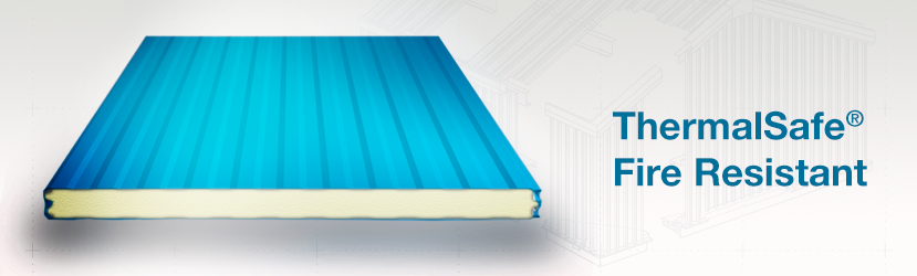
ThermalSafe® panel is the latest development in fire resistant wall construction technology.
ThermalSafe® combines advanced panel design with sophisticated manufacturing expertise to create a composite panel with a core made from non-combustible structural mineral wool boards that are processed in the factory to maximize compressive strength. The resulting panel has superior structural characteristics and span capability. This panel can achieve a one-, two- or three-hour fire resistance rating under the most demanding condtions. In addition to its fire resistance characteristics, the panel provides good thermal performance and protection from the elements. The unique LockGuard® interlocking side joint further enhances the fire resistant performance of the panel with its tongue and groove engagement of the mineral wool core.
ThermalSafe® fire resistant insulated panels are ideal for industrial buildings such as manufacturing plants, auxilliary buildings at refineries, and other at-risk for fire building installations. Warehouses of all types are excellent structures for mineral wool panels – either where they can be installed as exterior separation walls or as demising walls inside tilt-up warehouses with multiple tenant leased space.
Compare the Features and Benefits
Non-Combustible Core resists high temperatures and will not burn, providing excellent fire resistant qualities.
One-Step Construction process assures rapid completion of the wall system. Factory fabricated composite panels are attached directly to the supporting structure and multiple steps associated with installation of concrete blocks or numerous layers of gypsum wallboard are eliminated.
Superior Thermal Performance and protection from the elements across the entire wall area is assured with ThermalSafe® panels. The advanced mineral wool core provides enhanced insulated values that significantly lower heating and cooling costs.
Reusable Panels can be disassembled, moved and reinstalled rather than having to be demolished, the waste materials disposed of and the walls completely rebuilt.
Better Sound Absorption acoustical properties are achieved with ThermalSafe® compared to foam insulated metal panels.
Aesthetic Profile facing can be combined with the CF Light Mesa foam insulated wall panels for consistency in profile, texture and color.
| Exterior Profile: | Light Mesa Wave pattern, nominal 1/32” deep. | |||
| Interior Profile: | Light Mesa wave pattern, nominal 1/32″ deep. | |||
| Foam Core: | Non-combustible, rigid mineral wool lamellas. Mineral wool fibers are oriented perpendicular to the panel faces for maximum structural strength. | |||
| Thermal Value: | K-factor, Btu in/ft² hr °F @ 75°F mean core temperature = 0.275. |
|||
| R-Value: | The core insulating properties are 3.61 “R” per inch. | |||
| Module Width: | 42″ | |||
| Panel Thickness: | 3” TSNC*, 4”, 5”, 6”, 7” & 8” * 3” TSNC (ThermalSafe® Non-Combustible) does not have a fire rating, however can be applied as a non-combustible wall. |
|||
| Panel Lengths: | 8’-0” to 40’-0” variable by thickness. Contact Robertson for exact maximum length for each thickness. | |||
| Panel Weight 26 Ga. Faces: | 4″ – 4.65psf, 5″ – 5.49psf, 6″ – 6.21psf, 7″ – 6.92psf, 8″ – 7.63psf | |||
| Exterior Facings: | Stucco embossed, G-90 galvanized and/or AZ-50 aluminum-zinc coated steel in 26 Ga. and 24 Ga. | |||
| Interior Facings: | Stucco embossed, G-90 galvanized and/or AZ-50 aluminum-zinc coated steel in 26 Ga. and 24 Ga. Type 304 stainless steel in 26 Ga. embossed and unpainted. | |||
| Exterior Finishes & Colors: | Siliconized Polyester, Fluropon® Full-Strength 70% PVDF Fluoropolymer Coating.Note:1. Dark colors are not recommended for exterior color on cooler and freezer buildings.2. Prices may vary by color, gauge and quantity of metal. | |||
| Interior Finishes & Colors: | USDA-compliant Polyester, Igloo White. USDA-compliant PVC Plastisol Polar White. |
|||
| LockGuard® Joint: | Flush double tongue-and-groove interlock of the metal faces and machined integral spline of the mineral wool core. | |||
| Fastening: | Through fastening across the width of the panel to the support framing. Consult fire resistive listings for fastener types and spacing. Fastening patterns may vary depending on specific wind-load and fire resistive requirements. | |||
| FM Approved Class 1 with no height restrictions | ||||
| ThermalSafe® Fire Resistant Wall Panel | |||||||||||||
| Allowable Load for Single Span Condition (26 Ga. Exterior & 26 Ga. Interior Faces) | |||||||||||||
| TS Panel |
Design Criteria | Allowable Load (psf) per Panel Span (ft) | |||||||||||
| 5′ | 6′ | 7′ | 8′ | 9′ | 10′ | 11′ | 12′ | 13′ | 14′ | 15′ | |||
| 3″ Thick | Bending & Shear | 62.4 | 52.0 | 44.6 | 39.0 | 34.7 | 31.2 | 28.4 | 26.0 | 24.0 | 22.3 | 20.4 | |
| Deflection (L/240) | 85.2 | 65.9 | 52.0 | 41.7 | 33.9 | 27.8 | 23.0 | 19.2 | 16.2 | 13.7 | 11.7 | ||
| Connection F1 | 41.8 | 34.8 | 29.9 | 26.1 | 23.2 | 20.9 | 19.0 | 17.4 | 16.1 | 13.7 | 11.7 | ||
| 4″ Thick | Bending & Shear | 41.8 | 34.8 | 29.9 | 26.1 | 23.2 | 20.9 | 19.0 | 17.4 | 16.1 | 13.7 | 11.7 | |
| Deflection (L/240) | 79.3 | 66.1 | 56.7 | 49.6 | 44.1 | 39.7 | 36.1 | 33.1 | 30.5 | 28.3 | 26.3 | ||
| Connection F1 | 49.8 | 41.5 | 35.5 | 31.1 | 27.6 | 24.9 | 22.6 | 20.7 | 19.1 | 17.8 | 16.6 | ||
| 5″ Thick | Bending & Shear | 93.1 | 77.6 | 66.5 | 58.2 | 51.7 | 46.5 | 42.3 | 38.8 | 35.8 | 33.2 | 31.0 | |
| Deflection (L/240) | 140.1 | 111.7 | 91.0 | 75.4 | 63.2 | 53.4 | 45.6 | 39.1 | 33.7 | 29.3 | 25.5 | ||
| Connection F1 | 57.9 | 48.3 | 41.4 | 36.2 | 32.2 | 29.0 | 26.3 | 24.1 | 22.3 | 20.7 | 19.3 | ||
| 6″ Thick | Bending & Shear | 104.6 | 87.1 | 74.7 | 65.3 | 58.1 | 52.3 | 47.5 | 43.6 | 40.2 | 37.3 | 34.9 | |
| Deflection (L/240) | 162.4 | 130.5 | 107.4 | 89.8 | 76.0 | 65.0 | 55.9 | 48.5 | 42.2 | 37.0 | 32.5 | ||
| Connection F1 | 66.1 | 55.1 | 47.2 | 41.3 | 36.7 | 33.0 | 30.0 | 27.5 | 25.4 | 23.6 | 22.0 | ||
| 7″ Thick | Bending & Shear | 122.2 | 101.8 | 87.3 | 76.4 | 67.9 | 61.1 | 55.5 | 50.9 | 47.0 | 43.6 | 40.7 | |
| Deflection (L/240) | 192.0 | 155.1 | 128.3 | 107.9 | 91.8 | 78.9 | 68.4 | 59.6 | 52.2 | 45.9 | 40.6 | ||
| Connection F1 | 74.2 | 61.9 | 53.0 | 46.4 | 41.2 | 37.1 | 33.7 | 30.9 | 28.6 | 26.5 | 24.7 | ||
| 8″ Thick | Bending & Shear | 139.8 | 116.5 | 99.8 | 87.4 | 77.7 | 69.9 | 63.5 | 58.2 | 53.8 | 49.9 | 46.6 | |
| Deflection (L/240) | 221.7 | 179.7 | 149.3 | 126.1 | 107.8 | 93.1 | 81.0 | 70.9 | 62.4 | 55.2 | 49.0 | ||
| Connection F1 | 74.2 | 61.9 | 53.0 | 46.4 | 41.2 | 37.1 | 33.7 | 30.9 | 28.6 | 26.5 | 24.7 | ||
| ThermalSafe® Fire Resistant Wall Panel | |||||||||||||
| Allowable Load for Two or More Spans Condition (26 Ga. Exterior & 26 Ga. Interior Faces) |
|||||||||||||
| TS Panel |
Design Criteria | Allowable Load (psf) per Panel Span (ft) | |||||||||||
| 5′ | 6′ | 7′ | 8′ | 9′ | 10′ | 11′ | 12′ | 13′ | 14′ | 15′ | |||
| 3″ Thick | Bending & Shear | 55.2 | 45.4 | 38.5 | 33.4 | 29.5 | 26.3 | 23.7 | 21.6 | 19.8 | 18.3 | 17.0 | |
| Deflection (L/240) | 89.0 | 70.8 | 57.9 | 48.2 | 40.6 | 34.5 | 29.4 | 25.3 | 21.9 | 19.1 | 16.7 | ||
| Connection F1 | 46.5 | 39.7 | 33.4 | 28.8 | 25.3 | 22.6 | 20.4 | 18.6 | 17.0 | 15.8 | 14.7 | ||
| Connection F2 | 48.9 | 41.8 | 36.0 | 31.1 | 27.3 | 24.3 | 22.0 | 20.0 | 18.4 | 17.0 | 15.8 | ||
| 4″ Thick | Bending & Shear | 71.1 | 58.3 | 49.4 | 42.8 | 37.8 | 33.8 | 30.5 | 27.7 | 25.4 | 23.5 | 21.8 | |
| Deflection (L/240) | 117.2 | 94.0 | 77.5 | 65.2 | 55.6 | 48.0 | 41.6 | 36.3 | 31.8 | 28.0 | 24.7 | ||
| Connection F1 | 50.1 | 40.9 | 34.5 | 29.7 | 26.1 | 23.2 | 20.9 | 19.0 | 17.5 | 16.1 | 15.0 | ||
| Connection F2 | 56.1 | 46.8 | 39.5 | 34.0 | 29.9 | 26.6 | 23.9 | 21.8 | 20.0 | 18.5 | 17.1 | ||
| 5″ Thick | Bending & Shear | 85.3 | 69.9 | 59.2 | 51.2 | 45.2 | 40.4 | 36.5 | 33.3 | 30.5 | 28.1 | 26.1 | |
| Deflection (L/240) | 142.5 | 115.1 | 95.4 | 80.7 | 69.3 | 60.2 | 52.8 | 46.6 | 41.2 | 36.6 | 32.6 | ||
| Connection F1 | 51.4 | 42.0 | 35.4 | 30.5 | 26.8 | 23.8 | 21.4 | 19.5 | 17.9 | 16.5 | 15.3 | ||
| Connection F2 | 62.2 | 50.9 | 42.9 | 37.0 | 32.4 | 28.8 | 26.0 | 23.6 | 21.6 | 20.0 | 18.5 | ||
| 6″ Thick | Bending & Shear | 96.4 | 79.0 | 66.8 | 57.8 | 50.9 | 45.5 | 41.1 | 37.5 | 34.4 | 31.8 | 29.5 | |
| Deflection (L/240) | 164.2 | 133.2 | 111.0 | 94.3 | 81.4 | 71.0 | 62.6 | 55.6 | 49.7 | 44.5 | 39.9 | ||
| Connection F1 | 52.5 | 43.0 | 36.3 | 31.3 | 27.5 | 24.4 | 22.0 | 20.0 | 18.3 | 16.8 | 15.6 | ||
| Connection F2 | 67.0 | 54.9 | 46.3 | 39.9 | 35.0 | 31.1 | 28.0 | 25.5 | 23.3 | 21.5 | 19.9 | ||
| 7″ Thick | Bending & Shear | 113.4 | 93.0 | 78.6 | 68.0 | 59.8 | 53.4 | 48.2 | 44.0 | 40.4 | 37.4 | 34.7 | |
| Deflection (L/240) | 193.6 | 157.6 | 131.7 | 112.2 | 97.0 | 84.9 | 75.0 | 66.8 | 59.9 | 54.0 | 48.7 | ||
| Connection F1 | 53.4 | 43.9 | 37.0 | 31.9 | 28.0 | 24.9 | 22.4 | 20.3 | 18.6 | 17.2 | 15.9 | ||
| Connection F2 | 71.5 | 58.7 | 49.5 | 42.7 | 37.5 | 33.3 | 30.0 | 27.2 | 24.9 | 23.0 | 21.3 | ||
| 8″ Thick | Bending & Shear | 130.5 | 107.0 | 90.5 | 78.2 | 68.8 | 61.4 | 55.4 | 50.5 | 46.4 | 42.9 | 39.9 | |
| Deflection (L/240) | 223.2 | 182.0 | 152.4 | 130.1 | 112.8 | 98.9 | 87.6 | 78.2 | 70.3 | 63.5 | 57.6 | ||
| Connection F1 | 53.7 | 44.1 | 37.3 | 32.2 | 28.2 | 25.1 | 22.6 | 20.5 | 18.8 | 17.3 | 16.0 | ||
| Connection F2 | 71.9 | 59.0 | 49.9 | 43.0 | 37.8 | 33.6 | 30.2 | 27.4 | 25.1 | 23.1 | 21.4 | ||
Fastener Spacing across panel width into 14 Ga. Girts:
| ThermalSafe® Fire Resistant Wall Panel | |||||||||||||
| Thickness (in) |
Design Criteria | ||||||||||||
| Bending Stress | Shear Stress | Deflection Limit | Fastener Capacity | Allowable Span (ft) | |||||||||
| 3 | 30.3 | 62.3 | 21.2 | 41.8 | 21.2 | ||||||||
| 4 | 34.4 | 79.0 | 25.9 | 49.8 | 25.9 | ||||||||
| 5 | 37.8 | 93.5 | 30.1 | 57.9 | 30.1 | ||||||||
| 6 | 40.6 | 104.5 | 34.0 | 66.1 | 34.0 | ||||||||
| 7 | 43.9 | 122.1 | 37.9 | 74.2 | 37.9 | ||||||||
| 8 | 47.0 | 139.7 | 41.6 | 74.2 | 41.6 | ||||||||
| ThermalSafe® Fire Resistant Wall Panel | |||||||||||||
| Allowable Load for Single Span Condition (24 Ga. Exterior & 26 Ga. Interior Faces) | |||||||||||||
| TS Panel |
Design Criteria | Allowable Load (psf) per Panel Span (ft) | |||||||||||
| 5′ | 6′ | 7′ | 8′ | 9′ | 10′ | 11′ | 12′ | 13′ | 14′ | 15′ | |||
| 3″ Thick | Bending & Shear | 62.3 | 51.9 | 44.5 | 38.9 | 34.6 | 31.2 | 28.3 | 26.0 | 24.0 | 22.3 | 20.3 | |
| Deflection (L/240) | 86.8 | 67.5 | 53.7 | 43.3 | 35.4 | 29.3 | 24.4 | 20.5 | 17.3 | 14.8 | 12.6 | ||
| Connection F1 | 48.9 | 40.7 | 34.9 | 30.5 | 27.1 | 24.4 | 22.2 | 20.4 | 17.3 | 14.8 | 12.6 | ||
| 4″ Thick | Bending & Shear | 79.2 | 66.0 | 56.6 | 49.5 | 44.0 | 39.6 | 36.0 | 30.7 | 26.3 | 22.7 | 19.7 | |
| Deflection (L/240) | 115.7 | 91.6 | 74.1 | 60.9 | 50.7 | 42.6 | 36.0 | 30.7 | 26.3 | 22.7 | 19.7 | ||
| Connection F1 | 59.8 | 49.9 | 42.7 | 37.4 | 33.2 | 29.9 | 27.2 | 24.9 | 23.0 | 21.4 | 19.7 | ||
| 5″ Thick | Bending & Shear | 93.1 | 77.6 | 66.5 | 58.2 | 51.7 | 46.5 | 42.3 | 38.8 | 35.8 | 33.2 | 31.0 | |
| Deflection (L/240) | 141.6 | 113.4 | 92.8 | 77.3 | 65.1 | 55.3 | 47.4 | 40.9 | 35.4 | 30.9 | 27.0 | ||
| Connection F1 | 70.8 | 59.0 | 50.6 | 44.3 | 39.3 | 35.4 | 32.2 | 29.5 | 27.2 | 25.3 | 23.6 | ||
| 6″ Thick | Bending & Shear | 104.4 | 87.0 | 74.6 | 65.2 | 58.0 | 52.2 | 47.4 | 43.5 | 40.1 | 37.3 | 34.8 | |
| Deflection (L/240) | 163.7 | 132.1 | 109.1 | 91.7 | 77.9 | 66.9 | 57.9 | 50.3 | 44.0 | 38.7 | 34.2 | ||
| Connection F1 | 81.8 | 68.2 | 58.4 | 51.1 | 45.5 | 40.9 | 37.2 | 34.1 | 31.5 | 29.2 | 27.3 | ||
| 7″ Thick | Bending & Shear | 122.0 | 101.6 | 87.1 | 76.2 | 67.8 | 61.0 | 55.4 | 50.8 | 46.9 | 43.6 | 40.7 | |
| Deflection (L/240) | 193.4 | 156.7 | 130.1 | 109.8 | 93.9 | 81.0 | 70.4 | 61.6 | 54.2 | 47.9 | 42.5 | ||
| Connection F1 | 92.8 | 77.3 | 66.3 | 58.0 | 51.6 | 46.4 | 42.2 | 38.7 | 35.7 | 33.1 | 30.9 | ||
| 8″ Thick | Bending & Shear | 139.6 | 116.3 | 99.7 | 87.2 | 77.5 | 69.8 | 63.4 | 58.2 | 53.7 | 49.8 | 46.5 | |
| Deflection (L/240) | 223.2 | 181.4 | 151.1 | 128.1 | 109.9 | 95.3 | 83.2 | 73.1 | 64.6 | 57.4 | 51.1 | ||
| Connection F1 | 92.8 | 77.3 | 66.3 | 58.0 | 51.6 | 46.4 | 42.2 | 38.7 | 35.7 | 33.1 | 30.9 | ||
| ThermalSafe® Fire Resistant Wall Panel | |||||||||||||
| Allowable Load for Two or More Spans Condition (24 Ga. Exterior & 26 Ga. Interior Faces) |
|||||||||||||
| TS Panel |
Design Criteria | Allowable Load (psf) per Panel Span (ft) | |||||||||||
| 5′ | 6′ | 7′ | 8′ | 9′ | 10′ | 11′ | 12′ | 13′ | 14′ | 15′ | |||
| 3″ Thick | Bending & Shear | 55.5 | 45.6 | 38.6 | 33.5 | 29.6 | 26.4 | 23.8 | 21.7 | 19.9 | 18.4 | 17.1 | |
| Deflection (L/240) | 90.0 | 71.8 | 58.9 | 49.2 | 41.8 | 35.6 | 30.6 | 26.4 | 23.0 | 20.1 | 17.6 | ||
| Connection F1 | 53.9 | 45.6 | 38.6 | 33.5 | 29.6 | 26.4 | 23.8 | 21.7 | 19.9 | 18.4 | 17.1 | ||
| Connection F2 | 55.5 | 45.6 | 38.6 | 33.5 | 29.6 | 26.4 | 23.8 | 21.7 | 19.9 | 18.4 | 17.1 | ||
| 4″ Thick | Bending & Shear | 71.7 | 58.8 | 49.8 | 43.1 | 38.0 | 34.0 | 30.7 | 28.0 | 25.6 | 23.7 | 22.0 | |
| Deflection (L/240) | 118.2 | 95.1 | 78.6 | 66.3 | 56.7 | 49.1 | 42.9 | 37.5 | 33.0 | 29.1 | 25.9 | ||
| Connection F1 | 63.3 | 51.8 | 43.6 | 37.6 | 33.0 | 29.4 | 26.4 | 24.0 | 22.0 | 20.3 | 18.9 | ||
| Connection F2 | 69.5 | 57.3 | 48.3 | 41.6 | 36.5 | 32.5 | 29.3 | 26.6 | 24.4 | 22.5 | 20.9 | ||
| 5″ Thick | Bending & Shear | 85.3 | 69.9 | 59.1 | 51.1 | 45.1 | 40.3 | 36.4 | 33.2 | 30.5 | 28.1 | 26.1 | |
| Deflection (L/240) | 143.6 | 116.2 | 96.6 | 81.9 | 70.5 | 61.4 | 54.0 | 47.8 | 42.5 | 37.9 | 33.9 | ||
| Connection F1 | 66.7 | 54.6 | 46.1 | 39.7 | 34.8 | 31.0 | 27.9 | 25.3 | 23.2 | 21.4 | 19.9 | ||
| Connection F2 | 78.5 | 64.3 | 54.2 | 46.7 | 41.0 | 36.5 | 32.8 | 29.8 | 27.3 | 25.2 | 23.4 | ||
| 6″ Thick | Bending & Shear | 96.8 | 79.4 | 67.1 | 58.0 | 51.1 | 45.6 | 41.2 | 37.6 | 34.5 | 31.9 | 29.6 | |
| Deflection (L/240) | 165.2 | 134.3 | 112.2 | 95.5 | 82.6 | 72.2 | 63.8 | 56.8 | 50.8 | 45.8 | 41.2 | ||
| Connection F1 | 70.0 | 57.4 | 48.5 | 41.8 | 36.7 | 32.6 | 29.3 | 26.6 | 24.4 | 22.5 | 20.8 | ||
| Connection F2 | 86.9 | 71.3 | 60.2 | 51.9 | 45.5 | 40.5 | 36.4 | 33.1 | 30.3 | 27.9 | 25.9 | ||
| 7″ Thick | Bending & Shear | 113.9 | 93.4 | 78.9 | 68.2 | 60.1 | 53.6 | 48.4 | 44.1 | 40.5 | 37.5 | 34.8 | |
| Deflection (L/240) | 194.7 | 158.8 | 132.9 | 113.5 | 98.3 | 86.2 | 76.3 | 68.1 | 61.2 | 55.3 | 50.1 | ||
| Connection F1 | 73.0 | 60.0 | 50.7 | 43.7 | 38.4 | 34.1 | 30.7 | 27.9 | 25.5 | 23.5 | 21.8 | ||
| Connection F2 | 95.0 | 78.0 | 65.9 | 56.9 | 49.9 | 44.4 | 39.9 | 36.3 | 33.2 | 30.6 | 28.3 | ||
| 8″ Thick | Bending & Shear | 131.1 | 107.5 | 90.9 | 78.6 | 69.1 | 61.7 | 55.6 | 50.7 | 46.5 | 43.0 | 40.0 | |
| Deflection (L/240) | 224.3 | 183.3 | 153.8 | 131.5 | 114.2 | 100.4 | 89.0 | 79.6 | 71.6 | 64.8 | 59.0 | ||
| Connection F1 | 73.4 | 60.3 | 51.0 | 44.1 | 38.7 | 34.4 | 30.9 | 28.1 | 25.7 | 23.7 | 21.9 | ||
| Connection F2 | 95.4 | 78.5 | 66.4 | 57.3 | 50.3 | 44.7 | 40.2 | 36.5 | 33.4 | 30.8 | 28.5 | ||
Fastener Spacing across panel width into 14 Ga. Girts: