Contact Us: 800-387-5335
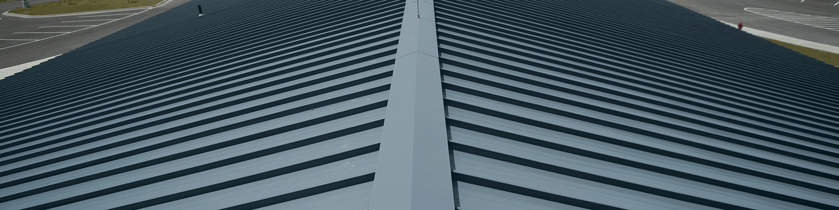
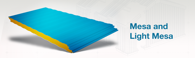
The Mesa & Light Mesa insulated metal wall panels are well suited for exterior wall and interior partition applications. The lightly corrugated profile on both faces of the panel ensures symmetry from outside the building to inside, and from room to room in partition applications. An aesthetically pleasing Mesa pattern is embossed on both interior and exterior skins. Mesa panels have a standard FM Approved Class 1 foam core and offer excellent insulating values. The metal and foam composite construction creates a rigid panel far stronger than the individual parts. This increases the span capability of the panel and reduces the need for secondary structural components.
FM Approved Class 1 with no height restrictions.
| Exterior Profile: | Mesa Wave Pattern, nominal 1/8″ deep. Light Mesa Wave Pattern, nominal 1/16″ deep. | |||
| Interior Profile: | Mesa wave pattern, nominal 1/8″ deep. Light Mesa wave pattern, nominal 1/16″ deep. | |||
| Foam Core: | Foamed-in-place, Non-CFC & zero ODP polyurethane, Factory Mutual Class 1 approval. | |||
| Thermal Value: | R-Values with Air Films | 75° Mean | 40° Mean | |
| 2″ Panel | 15.14 | 17.03 | ||
| 2-1/2″ Panel | 18.71 | 21.29 | ||
| 2-3/4″ Panel | 20.49 | 23.42 | ||
| 3″ Panel | 22.27 | 25.55 | ||
| 4″ Panel | 29.42 | 34.06 | ||
| 5″ Panel | 36.56 | 42.58 | ||
| 6″ Panel | 43.71 | 51.09 | ||
| • R-Values include the air films on each side of the panel• 75° Mean based on ASTM C518 Thermal Testing. 40° Mean based on ASTM C1363 Thermal Testing (Values for C1363 based on 4″ panel testing). All values for other thicknesses extrapolated | ||||
| Module Width: | 36″ & 42″ Partition Panel: 44-½” | |||
| Panel Thickness: | 2″, 2-½”, 2-¾”, 3″, 4″, 5″ & 6″ CF Light Mesa: 2″, 2-½”, 2-¾”, 3″ & 4″ | |||
| Panel Lengths: | Standard 8′-0″ to 53′-0″. | |||
| Exterior Facings: | Stucco embossed, G-90 galvanized and/or AZ-50 aluminum-zinc coated steel in 26 Ga., 24 Ga. and 22 Ga. | |||
| Interior Facings: | Stucco embossed, G-90 galvanized and/or AZ-50 aluminum-zinc coated steel in 26 Ga., 24 Ga. and 22 Ga. | |||
| Standard Exterior: | Full-Strength 70% PVDF Fluoropolymer Coating. | |||
| Finishes & Colors: | Polar White, Sandstone, Regal Gray, Desert Beige* and Dark Bronze*. *Desert Beige and Dark Bronze are premium colors in 22 Ga. thickness.Note:
|
|||
| Interior Finishes & Colors: | USDA-compliant Polyester, Igloo White. USDA-compliant PVC Plastisol, Polar White* *PVC Plastisol Polar White is a different color & shade than Polar White in other available finishes. | |||
| Joint: | Offset double tongue and groove with extended metal shelf for positive face fastening. Partition Panel: Offset double tongue and groove. | |||
| Fastening: | Fastener & Clip concealed in the side joint. Partition Panel: Through fastened at the top and bottom of the panel. | |||
| FM Approved Class 1 with no height restrictions. | ||||
| CF-42 MESA WALL PANEL ALLOWABLE CONNECTION LOAD (PSF) | |||||||||||||
| PANEL THICKNESS | SPAN CONDITION | FASTENING PATTERN | PANEL SPAN (FT) | ||||||||||
| 5 | 6 | 7 | 8 | 9 | 10 | 11 | 12 | 13 | 14 | 15 | |||
| 2″ Thick | Two Spans | Pattern FP1 | 31.6 | 25.8 | 21.7 | 18.8 | 16.5 | 14.8 | 13.3 | 12.2 | 11.2 | 10.3 | 9.6 |
| Pattern FP2 | 46.2 | 37.7 | 31.8 | 27.5 | 24.2 | 21.6 | 19.5 | 17.8 | 16.4 | 14.3 | 12.5 | ||
| Pattern FP3 | 58.3 | 47.6 | 40.2 | 34.7 | 30.5 | 26.0 | 22.1 | 19.0 | 16.4 | 14.3 | 12.5 | ||
| Three Or More Spans | Pattern FP1 | 33.1 | 27.4 | 23.4 | 20.4 | 18.1 | 16.2 | 14.7 | 13.5 | 12.4 | 11.5 | 10.8 | |
| Pattern FP2 | 48.4 | 40.1 | 34.2 | 29.8 | 26.4 | 23.7 | 21.2 | 18.0 | 15.4 | 13.2 | 11.4 | ||
| Pattern FP3 | 61.1 | 50.6 | 43.2 | 36.5 | 30.2 | 25.2 | 21.2 | 18.0 | 15.4 | 13.2 | 11.4 | ||
| 2.5″ Thick | Two Spans | Pattern FP1 | 33.3 | 27.2 | 22.9 | 19.8 | 17.4 | 15.5 | 14.0 | 12.7 | 11.7 | 10.8 | 10.1 |
| Pattern FP2 | 47.5 | 38.8 | 32.7 | 28.2 | 24.8 | 22.1 | 19.9 | 18.2 | 16.7 | 15.4 | 14.3 | ||
| Pattern FP3 | 60.1 | 49.0 | 41.3 | 35.7 | 31.4 | 28.0 | 25.2 | 23.0 | 21.1 | 19.5 | 17.3 | ||
| Three Or More Span | Pattern FP1 | 34.6 | 28.6 | 24.4 | 21.3 | 18.8 | 16.9 | 15.3 | 14.0 | 12.9 | 12.0 | 11.2 | |
| Pattern FP2 | 49.3 | 40.8 | 34.8 | 30.3 | 26.8 | 24.1 | 21.9 | 20.0 | 18.4 | 17.1 | 16.0 | ||
| Pattern FP3 | 62.4 | 51.6 | 44.0 | 38.3 | 33.9 | 30.5 | 27.7 | 24.7 | 21.3 | 18.5 | 16.2 | ||
| 3″ Thick | Two Spans | Pattern FP1 | 35.1 | 28.7 | 24.1 | 20.8 | 18.3 | 16.3 | 14.7 | 13.4 | 12.2 | 11.3 | 10.5 |
| Pattern FP2 | 48.8 | 39.8 | 33.6 | 28.9 | 25.4 | 22.6 | 20.4 | 18.6 | 17.0 | 15.7 | 14.6 | ||
| Pattern FP3 | 61.8 | 50.5 | 42.5 | 36.7 | 32.2 | 28.7 | 25.9 | 23.5 | 21.6 | 20.0 | 18.6 | ||
| Pattern FP4 | 71.1 | 58.0 | 48.9 | 42.2 | 37.0 | 33.0 | 29.7 | 27.1 | 24.8 | 22.9 | 21.3 | ||
| Three Or More Spans | Pattern FP1 | 36.1 | 29.9 | 25.4 | 22.2 | 19.6 | 17.6 | 16.0 | 14.6 | 13.5 | 12.5 | 11.6 | |
| Pattern FP2 | 50.2 | 41.5 | 35.4 | 30.8 | 27.3 | 24.5 | 22.2 | 20.3 | 18.7 | 17.4 | 16.2 | ||
| Pattern FP3 | 63.7 | 52.6 | 44.8 | 39.0 | 34.6 | 31.0 | 28.2 | 25.8 | 23.7 | 22.0 | 20.5 | ||
| Pattern FP4 | 73.2 | 60.5 | 51.5 | 44.9 | 39.7 | 35.7 | 32.4 | 29.6 | 27.2 | 23.8 | 21.0 | ||
| 4″ Thick | Two Spans | Pattern FP1 | 43.0 | 35.3 | 29.8 | 25.6 | 22.5 | 20.0 | 18.0 | 16.4 | 15.0 | 13.8 | 12.8 |
| Pattern FP2 | 63.0 | 51.8 | 43.6 | 37.6 | 33.0 | 29.3 | 26.4 | 24.0 | 22.0 | 20.3 | 18.8 | ||
| Pattern FP3 | 74.3 | 61.0 | 51.5 | 44.3 | 38.9 | 34.6 | 31.2 | 28.3 | 26.0 | 23.9 | 22.2 | ||
| Pattern FP4 | 79.6 | 65.4 | 55.1 | 47.5 | 41.7 | 37.1 | 33.4 | 30.3 | 27.8 | 25.7 | 23.8 | ||
| Pattern FP5 | 83.3 | 68.4 | 57.7 | 49.7 | 43.6 | 38.8 | 34.9 | 31.7 | 29.1 | 26.8 | 24.9 | ||
| Pattern FP9 | 89.5 | 73.5 | 62.0 | 53.4 | 46.9 | 41.7 | 37.5 | 34.1 | 31.3 | 28.8 | 26.8 | ||
| Pattern FP10 | 93.6 | 76.9 | 64.8 | 55.9 | 49.0 | 43.6 | 39.3 | 35.7 | 32.7 | 30.2 | 28.0 | ||
| Three Or More Spans | Pattern FP1 | 44.0 | 36.3 | 30.9 | 26.9 | 23.8 | 21.3 | 19.3 | 17.7 | 16.3 | 15.1 | 14.1 | |
| Pattern FP2 | 64.4 | 53.2 | 45.3 | 39.4 | 34.9 | 31.3 | 28.3 | 25.9 | 23.9 | 22.1 | 20.6 | ||
| Pattern FP3 | 76.0 | 62.8 | 53.4 | 46.5 | 41.1 | 36.9 | 33.4 | 30.6 | 28.2 | 26.1 | 24.3 | ||
| Pattern FP4 | 81.4 | 67.2 | 57.2 | 49.8 | 44.1 | 39.5 | 35.8 | 32.8 | 30.2 | 28.0 | 26.1 | ||
| Pattern FP5 | 85.1 | 70.3 | 59.9 | 52.1 | 46.1 | 41.3 | 37.5 | 34.3 | 31.6 | 29.3 | 27.3 | ||
| Pattern FP9 | 91.5 | 75.6 | 64.2 | 55.6 | 49.0 | 43.8 | 39.6 | 36.2 | 33.3 | 30.8 | 28.7 | ||
| Pattern FP10 | 92.6 | 75.9 | 64.2 | 55.6 | 49.0 | 43.8 | 39.6 | 36.2 | 33.3 | 30.8 | 28.7 | ||
| 5″ Thick | Two Spans | Pattern FP1 | 42.3 | 35.8 | 30.3 | 26.2 | 23.0 | 20.4 | 18.4 | 16.7 | 15.3 | 14.1 | 13.0 |
| Pattern FP2 | 61.9 | 52.5 | 44.5 | 38.4 | 33.6 | 29.9 | 26.9 | 24.4 | 22.4 | 20.6 | 19.1 | ||
| Pattern FP3 | 73.1 | 62.0 | 52.5 | 45.2 | 39.7 | 35.3 | 31.7 | 28.8 | 26.4 | 24.3 | 22.6 | ||
| Pattern FP4 | 78.2 | 66.4 | 56.2 | 48.5 | 42.5 | 37.8 | 34.0 | 30.9 | 28.3 | 26.1 | 24.2 | ||
| Pattern FP5 | 81.9 | 69.4 | 58.8 | 50.7 | 44.5 | 39.6 | 35.6 | 32.3 | 29.6 | 27.3 | 25.3 | ||
| Pattern FP9 | 88.0 | 74.6 | 63.2 | 54.5 | 47.8 | 42.5 | 38.2 | 34.7 | 31.8 | 29.3 | 27.2 | ||
| Pattern FP10 | 92.0 | 78.1 | 66.1 | 57.0 | 50.0 | 44.5 | 40.0 | 36.3 | 33.3 | 30.7 | 28.4 | ||
| Three Or More Spans | Pattern FP1 | 43.5 | 36.6 | 31.2 | 27.1 | 24.0 | 21.5 | 19.4 | 17.8 | 16.4 | 15.2 | 14.1 | |
| Pattern FP2 | 63.8 | 53.7 | 45.7 | 39.7 | 35.1 | 31.5 | 28.5 | 26.1 | 24.0 | 22.2 | 20.7 | ||
| Pattern FP3 | 75.2 | 63.3 | 53.9 | 46.8 | 41.4 | 37.1 | 33.6 | 30.7 | 28.3 | 26.2 | 24.4 | ||
| Pattern FP4 | 80.6 | 67.8 | 57.7 | 50.2 | 44.4 | 39.8 | 36.0 | 32.9 | 30.3 | 28.1 | 26.2 | ||
| Pattern FP5 | 84.3 | 70.9 | 60.4 | 52.5 | 46.4 | 41.6 | 37.7 | 34.4 | 31.7 | 29.4 | 27.4 | ||
| Pattern FP9 | 90.6 | 76.2 | 64.9 | 56.4 | 49.9 | 44.7 | 40.5 | 37.0 | 34.1 | 31.6 | 29.4 | ||
| Pattern FP10 | 94.8 | 79.8 | 67.9 | 59.0 | 52.2 | 46.8 | 42.4 | 38.7 | 35.7 | 33.0 | 30.8 | ||
| 6″ Thick | Two Spans | Pattern FP1 | 41.7 | 35.3 | 30.7 | 26.6 | 23.4 | 20.8 | 18.7 | 17.0 | 15.5 | 14.3 | 13.2 |
| Pattern FP2 | 61.2 | 51.7 | 45.0 | 39.0 | 34.3 | 30.5 | 27.4 | 24.9 | 22.8 | 21.0 | 19.4 | ||
| Pattern FP3 | 72.1 | 61.0 | 53.0 | 46.0 | 40.4 | 36.0 | 32.3 | 29.4 | 26.9 | 24.7 | 22.9 | ||
| Pattern FP4 | 77.2 | 65.3 | 56.8 | 49.3 | 43.3 | 38.5 | 34.6 | 31.4 | 28.8 | 26.5 | 24.5 | ||
| Pattern FP5 | 80.8 | 68.3 | 59.4 | 51.6 | 45.3 | 40.3 | 36.2 | 32.9 | 30.1 | 27.7 | 25.7 | ||
| Pattern FP9 | 86.9 | 73.4 | 63.9 | 55.5 | 48.7 | 43.3 | 39.0 | 35.4 | 32.3 | 29.8 | 27.6 | ||
| Pattern FP10 | 90.9 | 76.8 | 66.8 | 58.0 | 50.9 | 45.3 | 40.7 | 37.0 | 33.8 | 31.2 | 28.9 | ||
| Three Or More Spans | Pattern FP1 | 42.8 | 36.3 | 31.4 | 27.3 | 24.1 | 21.6 | 19.6 | 17.9 | 16.4 | 15.2 | 14.2 | |
| Pattern FP2 | 62.7 | 53.2 | 46.0 | 40.0 | 35.4 | 31.7 | 28.7 | 26.2 | 24.1 | 22.3 | 20.8 | ||
| Pattern FP3 | 74.0 | 62.8 | 54.3 | 47.2 | 41.7 | 37.4 | 33.8 | 30.9 | 28.4 | 26.3 | 24.5 | ||
| Pattern FP4 | 79.3 | 67.2 | 58.1 | 50.5 | 44.7 | 40.0 | 36.2 | 33.1 | 30.5 | 28.2 | 26.3 | ||
| Pattern FP5 | 82.9 | 70.3 | 60.8 | 52.9 | 46.7 | 41.9 | 37.9 | 34.6 | 31.9 | 29.5 | 27.5 | ||
| Pattern FP9 | 89.1 | 75.6 | 65.4 | 56.8 | 50.2 | 45.0 | 40.8 | 37.2 | 34.3 | 31.7 | 29.6 | ||
| Pattern FP10 | 93.2 | 79.1 | 68.4 | 59.5 | 52.6 | 47.1 | 42.6 | 38.9 | 35.8 | 33.2 | 30.9 | ||
| CF-36 MESA WALL PANEL ALLOWABLE CONNECTION LOAD (PSF) | ||||||||||
| PANEL THICKENSS | SPAN CONDITION | FASTENING PATTERN | PANEL SPAN (FT) | |||||||
| 5 | 6 | 7 | 8 | 9 | 10 | 11 | 12 | |||
| 2″ Thick | Two Spans | Pattern FP1 | 40.5 | 34.6 | 30.3 | 26.8 | 23.6 | 21.0 | 19.0 | 17.3 |
| 2.5″ Thick | Pattern FP1 | 45.0 | 38.5 | 33.7 | 30.1 | 27.1 | 24.1 | 21.8 | 19.8 | |
| 3″ Thick | Pattern FP1 | 49.0 | 41.8 | 36.6 | 32.7 | 29.5 | 26.9 | 24.3 | 22.2 | |
| 2″ Thick | Three Or More Spans | Pattern FP1 | 41.4 | 35.1 | 30.4 | 26.8 | 24.0 | 21.7 | 19.8 | 18.2 |
| 2.5″ Thick | Pattern FP1 | 46.3 | 39.3 | 34.1 | 30.2 | 27.0 | 24.4 | 22.3 | 20.5 | |
| 3″ Thick | Pattern FP1 | 50.5 | 42.9 | 37.3 | 33.1 | 29.6 | 26.9 | 24.6 | 22.6 | |
| CF-30 MESA WALL PANEL ALLOWABLE CONNECTION LOAD (PSF) | ||||||||||
| PANEL THICKENSS | SPAN CONDITION | FASTENING PATTERN | PANEL SPAN (FT) | |||||||
| 5 | 6 | 7 | 8 | 9 | 10 | 11 | 12 | |||
| 2″ Thick | Two Spans | Pattern FP1 | 48.6 | 41.6 | 36.4 | 32.1 | 28.3 | 25.2 | 21.2 | 17.3 |
| 2.5″ Thick | Pattern FP1 | 54.1 | 46.2 | 40.5 | 36.1 | 32.5 | 29.0 | 26.1 | 21.5 | |
| 3″ Thick | Pattern FP1 | 58.8 | 50.2 | 44.0 | 39.2 | 35.4 | 32.3 | 29.2 | 25.5 | |
| 2″ Thick | Three Or More Spans | Pattern FP1 | 49.7 | 42.1 | 36.5 | 32.2 | 28.8 | 26.0 | 22.0 | 18.7 |
| 2.5″ Thick | Pattern FP1 | 55.6 | 47.1 | 41.0 | 36.2 | 32.4 | 29.3 | 26.8 | 23.7 | |
| 3″ Thick | Pattern FP1 | 60.6 | 51.5 | 44.8 | 39.7 | 35.6 | 32.2 | 29.5 | 27.1 | |
| CF MESA WALL PANEL ALLOWABLE POSITIVE LOAD (PSF) | |||||||||||||
| PANEL THICKNESS | SPAN CONDITION | DESIGN CRITERIA | PANEL SPAN (FT) | ||||||||||
| 5 | 6 | 7 | 8 | 9 | 10 | 11 | 12 | 13 | 14 | 15 | |||
| 2″ Thick | Two Spans | Bending & Shear | 68.7 | 56.1 | 47.3 | 40.9 | 36.0 | 32.1 | 29.0 | 26.5 | 22.2 | 18.8 | 16.1 |
| Deflection (L/180) | 70.0 | 55.1 | 44.6 | 36.7 | 30.7 | 26.0 | 22.1 | 19.0 | 16.4 | 14.3 | 12.5 | ||
| Three Or More Spans | Bending & Shear | 67.5 | 55.6 | 47.2 | 41.1 | 36.4 | 32.6 | 29.6 | 27.0 | 24.9 | 21.9 | 18.9 | |
| Deflection (L/180) | 70.8 | 55.6 | 44.6 | 36.5 | 30.2 | 25.2 | 21.2 | 18.0 | 15.4 | 13.2 | 11.4 | ||
| 2.5″ Thick | Two Spans | Bending & Shear | 79.3 | 64.8 | 54.6 | 47.1 | 41.4 | 36.9 | 33.3 | 30.4 | 27.1 | 22.8 | 19.4 |
| Deflection (L/180) | 87.9 | 69.9 | 57.0 | 47.5 | 40.1 | 34.2 | 29.5 | 25.6 | 22.3 | 19.6 | 17.3 | ||
| Three Or More Spans | Bending & Shear | 77.6 | 63.8 | 54.1 | 47.0 | 41.6 | 37.2 | 33.7 | 30.9 | 28.4 | 25.9 | 22.4 | |
| Deflection (L/180) | 88.9 | 70.6 | 57.5 | 47.6 | 39.9 | 33.7 | 28.8 | 24.7 | 21.3 | 18.5 | 16.2 | ||
| 3″ Thick | Two Spans | Bending & Shear | 89.0 | 72.7 | 61.2 | 52.8 | 46.4 | 41.3 | 37.2 | 33.9 | 31.1 | 26.7 | 22.7 |
| Deflection (L/180) | 104.1 | 83.3 | 68.4 | 57.3 | 48.8 | 41.9 | 36.4 | 31.8 | 28.0 | 24.8 | 22.0 | ||
| Three Or More Spans | Bending & Shear | 86.9 | 71.3 | 60.4 | 52.4 | 46.3 | 41.4 | 37.5 | 34.3 | 31.6 | 29.2 | 25.6 | |
| Deflection (L/180) | 105.2 | 84.3 | 69.2 | 57.8 | 48.9 | 41.8 | 36.0 | 31.2 | 27.2 | 23.8 | 21.0 | ||
| 4″ Thick | Two Spans | Bending & Shear | 95.1 | 77.8 | 65.6 | 56.5 | 49.6 | 44.1 | 39.7 | 36.1 | 33.1 | 30.5 | 28.3 |
| Deflection (L/180) | 130.8 | 105.6 | 87.6 | 74.1 | 63.6 | 55.2 | 48.4 | 42.8 | 38.1 | 34.0 | 30.6 | ||
| Three Or More Spans | Bending & Shear | 92.6 | 75.9 | 64.2 | 55.6 | 49.0 | 43.8 | 39.6 | 36.2 | 33.3 | 30.8 | 28.7 | |
| Deflection (L/180) | 131.7 | 106.6 | 88.6 | 74.9 | 64.2 | 55.6 | 48.6 | 42.7 | 37.8 | 33.5 | 29.9 | ||
| 5″ Thick | Two Spans | Bending & Shear | 108.8 | 89.3 | 75.4 | 65.0 | 57.0 | 50.7 | 45.6 | 41.4 | 37.9 | 35.0 | 32.4 |
| Deflection (L/180) | 149.1 | 121.2 | 101.2 | 86.2 | 74.5 | 65.1 | 57.5 | 51.2 | 45.8 | 41.3 | 37.4 | ||
| Three Or More Spans | Bending & Shear | 106.1 | 87.0 | 73.5 | 63.6 | 56.0 | 50.0 | 45.1 | 41.2 | 37.8 | 35.0 | 32.5 | |
| Deflection (L/180) | 149.9 | 122.1 | 102.2 | 87.1 | 75.3 | 65.9 | 58.1 | 51.5 | 46.0 | 41.3 | 37.2 | ||
| 6″ Thick | Two Spans | Bending & Shear | 121.2 | 99.7 | 84.3 | 72.8 | 63.9 | 56.9 | 51.2 | 46.4 | 42.5 | 39.1 | 36.3 |
| Deflection (L/180) | 159.0 | 129.9 | 109.1 | 93.3 | 81.1 | 71.3 | 63.3 | 56.6 | 51.0 | 46.1 | 42.0 | ||
| Three Or More Spans | Bending & Shear | 118.5 | 97.2 | 82.1 | 71.0 | 62.5 | 55.7 | 50.3 | 45.8 | 42.0 | 38.9 | 36.1 | |
| Deflection (L/180) | 159.5 | 130.6 | 109.8 | 94.2 | 81.9 | 72.1 | 64.0 | 57.2 | 51.4 | 46.5 | 42.2 | ||
| CF-42 LIGHT MESA WALL PANEL ALLOWABLE CONNECTION LOAD (PSF) | |||||||||||||
| PANEL THICKNESS | SPAN CONDITION | FASTENING PATTERN | PANEL SPAN (FT) | ||||||||||
| 5 | 6 | 7 | 8 | 9 | 10 | 11 | 12 | 13 | 14 | 15 | |||
| 2″ Thick | Two Spans | Pattern FP1 | 31.6 | 25.8 | 21.7 | 18.8 | 16.5 | 14.8 | 13.3 | 12.2 | 11.2 | 10.3 | 9.6 |
| Pattern FP2 | 46.2 | 37.7 | 31.8 | 27.5 | 24.2 | 21.6 | 19.5 | 17.8 | 16.4 | 14.3 | 12.5 | ||
| Pattern FP3 | 58.3 | 47.6 | 40.2 | 34.7 | 30.5 | 26.0 | 22.1 | 19.0 | 16.4 | 14.3 | 12.5 | ||
| Three Or More Spans | Pattern FP1 | 33.1 | 27.4 | 23.4 | 20.4 | 18.1 | 16.2 | 14.7 | 13.5 | 12.4 | 11.5 | 10.8 | |
| Pattern FP2 | 48.4 | 40.1 | 34.2 | 29.8 | 26.4 | 23.7 | 21.2 | 18.0 | 15.4 | 13.2 | 11.4 | ||
| Pattern FP3 | 61.1 | 50.6 | 43.2 | 36.5 | 30.2 | 25.2 | 21.2 | 18.0 | 15.4 | 13.2 | 11.4 | ||
| 2.5″ Thick | Two Spans | Pattern FP1 | 33.3 | 27.2 | 22.9 | 19.8 | 17.4 | 15.5 | 14.0 | 12.7 | 11.7 | 10.8 | 10.1 |
| Pattern FP2 | 47.5 | 38.8 | 32.7 | 28.2 | 24.8 | 22.1 | 19.9 | 18.2 | 16.7 | 15.4 | 14.3 | ||
| Pattern FP3 | 60.1 | 49.0 | 41.3 | 35.7 | 31.4 | 28.0 | 25.2 | 23.0 | 21.1 | 19.5 | 17.3 | ||
| Three Or More Spans | Pattern FP1 | 34.6 | 28.6 | 24.4 | 21.3 | 18.8 | 16.9 | 15.3 | 14.0 | 12.9 | 12.0 | 11.2 | |
| Pattern FP2 | 49.3 | 40.8 | 34.8 | 30.3 | 26.8 | 24.1 | 21.9 | 20.0 | 18.4 | 17.1 | 16.0 | ||
| Pattern FP3 | 62.4 | 51.6 | 44.0 | 38.3 | 33.9 | 30.5 | 27.7 | 24.7 | 21.3 | 18.5 | 16.2 | ||
| 3″ Thick | Two Spans | Pattern FP1 | 35.1 | 28.7 | 24.1 | 20.8 | 18.3 | 16.3 | 14.7 | 13.4 | 12.2 | 11.3 | 10.5 |
| Pattern FP2 | 48.8 | 39.8 | 33.6 | 28.9 | 25.4 | 22.6 | 20.4 | 18.6 | 17.0 | 15.7 | 14.6 | ||
| Pattern FP3 | 61.8 | 50.5 | 42.5 | 36.7 | 32.2 | 28.7 | 25.9 | 23.5 | 21.6 | 20.0 | 18.6 | ||
| Pattern FP4 | 71.1 | 58.0 | 48.9 | 42.2 | 37.0 | 33.0 | 29.7 | 27.1 | 24.8 | 22.9 | 21.3 | ||
| Three Or More Spans | Pattern FP1 | 36.1 | 29.9 | 25.4 | 22.2 | 19.6 | 17.6 | 16.0 | 14.6 | 13.5 | 12.5 | 11.6 | |
| Pattern FP2 | 50.2 | 41.5 | 35.4 | 30.8 | 27.3 | 24.5 | 22.2 | 20.3 | 18.7 | 17.4 | 16.2 | ||
| Pattern FP3 | 63.7 | 52.6 | 44.8 | 39.0 | 34.6 | 31.0 | 28.2 | 25.8 | 23.7 | 22.0 | 20.5 | ||
| Pattern FP4 | 73.2 | 60.5 | 51.5 | 44.9 | 39.7 | 35.7 | 32.4 | 29.6 | 27.2 | 23.8 | 21.0 | ||
| 4″ Thick | Two Spans | Pattern FP1 | 43.0 | 35.3 | 29.8 | 25.6 | 22.5 | 20.0 | 18.0 | 16.4 | 15.0 | 13.8 | 12.8 |
| Pattern FP2 | 63.0 | 51.8 | 43.6 | 37.6 | 33.0 | 29.3 | 26.4 | 24.0 | 22.0 | 20.3 | 18.8 | ||
| Pattern FP3 | 74.3 | 61.0 | 51.5 | 44.3 | 38.9 | 34.6 | 31.2 | 28.3 | 26.0 | 23.9 | 22.2 | ||
| Pattern FP4 | 79.6 | 65.4 | 55.1 | 47.5 | 41.7 | 37.1 | 33.4 | 30.3 | 27.8 | 25.7 | 23.8 | ||
| Pattern FP5 | 83.3 | 68.4 | 57.7 | 49.7 | 43.6 | 38.8 | 34.9 | 31.7 | 29.1 | 26.8 | 24.9 | ||
| Pattern FP9 | 89.5 | 73.5 | 62.0 | 53.4 | 46.9 | 41.7 | 37.5 | 34.1 | 31.3 | 28.8 | 26.8 | ||
| Pattern FP10 | 93.6 | 76.9 | 64.8 | 55.9 | 49.0 | 43.6 | 39.3 | 35.7 | 32.7 | 30.2 | 28.0 | ||
| Three Or More Spans | Pattern FP1 | 44.0 | 36.3 | 30.9 | 26.9 | 23.8 | 21.3 | 19.3 | 17.7 | 16.3 | 15.1 | 14.1 | |
| Pattern FP2 | 64.4 | 53.2 | 45.3 | 39.4 | 34.9 | 31.3 | 28.3 | 25.9 | 23.9 | 22.1 | 20.6 | ||
| Pattern FP3 | 76.0 | 62.8 | 53.4 | 46.5 | 41.1 | 36.9 | 33.4 | 30.6 | 28.2 | 26.1 | 24.3 | ||
| Pattern FP4 | 81.4 | 67.2 | 57.2 | 49.8 | 44.1 | 39.5 | 35.8 | 32.8 | 30.2 | 28.0 | 26.1 | ||
| Pattern FP5 | 85.1 | 70.3 | 59.9 | 52.1 | 46.1 | 41.3 | 37.5 | 34.3 | 31.6 | 29.3 | 27.3 | ||
| Pattern FP9 | 91.5 | 75.6 | 64.2 | 55.6 | 49.0 | 43.8 | 39.6 | 36.2 | 33.3 | 30.8 | 28.7 | ||
| Pattern FP10 | 92.6 | 75.9 | 64.2 | 55.6 | 49.0 | 43.8 | 39.6 | 36.2 | 33.3 | 30.8 | 28.7 | ||
| 5″ Thick | Two Spans | Pattern FP1 | 42.3 | 35.8 | 30.3 | 26.2 | 23.0 | 20.4 | 18.4 | 16.7 | 15.3 | 14.1 | 13.0 |
| Pattern FP2 | 61.9 | 52.5 | 44.5 | 38.4 | 33.6 | 29.9 | 26.9 | 24.4 | 22.4 | 20.6 | 19.1 | ||
| Pattern FP3 | 73.1 | 62.0 | 52.5 | 45.2 | 39.7 | 35.3 | 31.7 | 28.8 | 26.4 | 24.3 | 22.6 | ||
| Pattern FP4 | 78.2 | 66.4 | 56.2 | 48.5 | 42.5 | 37.8 | 34.0 | 30.9 | 28.3 | 26.1 | 24.2 | ||
| Pattern FP5 | 81.9 | 69.4 | 58.8 | 50.7 | 44.5 | 39.6 | 35.6 | 32.3 | 29.6 | 27.3 | 25.3 | ||
| Pattern FP9 | 88.0 | 74.6 | 63.2 | 54.5 | 47.8 | 42.5 | 38.2 | 34.7 | 31.8 | 29.3 | 27.2 | ||
| Pattern FP10 | 92.0 | 78.1 | 66.1 | 57.0 | 50.0 | 44.5 | 40.0 | 36.3 | 33.3 | 30.7 | 28.4 | ||
| Three Or More Spans | Pattern FP1 | 43.5 | 36.6 | 31.2 | 27.1 | 24.0 | 21.5 | 19.4 | 17.8 | 16.4 | 15.2 | 14.1 | |
| Pattern FP2 | 63.8 | 53.7 | 45.7 | 39.7 | 35.1 | 31.5 | 28.5 | 26.1 | 24.0 | 22.2 | 20.7 | ||
| Pattern FP3 | 75.2 | 63.3 | 53.9 | 46.8 | 41.4 | 37.1 | 33.6 | 30.7 | 28.3 | 26.2 | 24.4 | ||
| Pattern FP4 | 80.6 | 67.8 | 57.7 | 50.2 | 44.4 | 39.8 | 36.0 | 32.9 | 30.3 | 28.1 | 26.2 | ||
| Pattern FP5 | 84.3 | 70.9 | 60.4 | 52.5 | 46.4 | 41.6 | 37.7 | 34.4 | 31.7 | 29.4 | 27.4 | ||
| Pattern FP9 | 90.6 | 76.2 | 64.9 | 56.4 | 49.9 | 44.7 | 40.5 | 37.0 | 34.1 | 31.6 | 29.4 | ||
| Pattern FP10 | 94.8 | 79.8 | 67.9 | 59.0 | 52.2 | 46.8 | 42.4 | 38.7 | 35.7 | 33.0 | 30.8 | ||
| 6″ Thick | Two Spans | Pattern FP1 | 41.7 | 35.3 | 30.7 | 26.6 | 23.4 | 20.8 | 18.7 | 17.0 | 15.5 | 14.3 | 13.2 |
| Pattern FP2 | 61.2 | 51.7 | 45.0 | 39.0 | 34.3 | 30.5 | 27.4 | 24.9 | 22.8 | 21.0 | 19.4 | ||
| Pattern FP3 | 72.1 | 61.0 | 53.0 | 46.0 | 40.4 | 36.0 | 32.3 | 29.4 | 26.9 | 24.7 | 22.9 | ||
| Pattern FP4 | 77.2 | 65.3 | 56.8 | 49.3 | 43.3 | 38.5 | 34.6 | 31.4 | 28.8 | 26.5 | 24.5 | ||
| Pattern FP5 | 80.8 | 68.3 | 59.4 | 51.6 | 45.3 | 40.3 | 36.2 | 32.9 | 30.1 | 27.7 | 25.7 | ||
| Pattern FP9 | 86.9 | 73.4 | 63.9 | 55.5 | 48.7 | 43.3 | 39.0 | 35.4 | 32.3 | 29.8 | 27.6 | ||
| Pattern FP10 | 90.9 | 76.8 | 66.8 | 58.0 | 50.9 | 45.3 | 40.7 | 37.0 | 33.8 | 31.2 | 28.9 | ||
| Three Or More Spans | Pattern FP1 | 42.8 | 36.3 | 31.4 | 27.3 | 24.1 | 21.6 | 19.6 | 17.9 | 16.4 | 15.2 | 14.2 | |
| Pattern FP2 | 62.7 | 53.2 | 46.0 | 40.0 | 35.4 | 31.7 | 28.7 | 26.2 | 24.1 | 22.3 | 20.8 | ||
| Pattern FP3 | 74.0 | 62.8 | 54.3 | 47.2 | 41.7 | 37.4 | 33.8 | 30.9 | 28.4 | 26.3 | 24.5 | ||
| Pattern FP4 | 79.3 | 67.2 | 58.1 | 50.5 | 44.7 | 40.0 | 36.2 | 33.1 | 30.5 | 28.2 | 26.3 | ||
| Pattern FP5 | 82.9 | 70.3 | 60.8 | 52.9 | 46.7 | 41.9 | 37.9 | 34.6 | 31.9 | 29.5 | 27.5 | ||
| Pattern FP9 | 89.1 | 75.6 | 65.4 | 56.8 | 50.2 | 45.0 | 40.8 | 37.2 | 34.3 | 31.7 | 29.6 | ||
| Pattern FP10 | 93.2 | 79.1 | 68.4 | 59.5 | 52.6 | 47.1 | 42.6 | 38.9 | 35.8 | 33.2 | 30.9 | ||
| CF-36 LIGHT MESA WALL PANEL ALLOWABLE CONNECTION LOAD (PSF) | ||||||||||
| PANEL THICKNESS | SPAN CONDITION | FASTENING PATTERN | PANEL SPAN (FT) | |||||||
| 5 | 6 | 7 | 8 | 9 | 10 | 11 | 12 | |||
| 2″ Thick | Two Spans | Pattern FP1 | 40.5 | 34.6 | 30.3 | 26.8 | 23.6 | 21.0 | 19.0 | 17.3 |
| 2.5″ Thick | Pattern FP1 | 45.0 | 38.5 | 33.7 | 30.1 | 27.1 | 24.1 | 21.8 | 19.8 | |
| 3″ Thick | Pattern FP1 | 49.0 | 41.8 | 36.6 | 32.7 | 29.5 | 26.9 | 24.3 | 22.2 | |
| 2″ Thick | Three Or More Spans | Pattern FP1 | 41.4 | 35.1 | 30.4 | 26.8 | 24.0 | 21.7 | 19.8 | 18.2 |
| 2.5″ Thick | Pattern FP1 | 46.3 | 39.3 | 34.1 | 30.2 | 27.0 | 24.4 | 22.3 | 20.5 | |
| 3″ Thick | Pattern FP1 | 50.5 | 42.9 | 37.3 | 33.1 | 29.6 | 26.9 | 24.6 | 22.6 | |
| CF-30 LIGHT MESA WALL PANEL ALLOWABLE CONNECTION LOAD (PSF) | ||||||||||
| PANEL THICKNESS | SPAN CONDITION | FASTENING PATTERN | PANEL SPAN (FT) | |||||||
| 5 | 6 | 7 | 8 | 9 | 10 | 11 | 12 | |||
| 2″ Thick | Two Spans | Pattern FP1 | 48.6 | 41.6 | 36.4 | 32.1 | 28.3 | 25.2 | 21.2 | 17.3 |
| 2.5″ Thick | Pattern FP1 | 54.1 | 46.2 | 40.5 | 36.1 | 32.5 | 29.0 | 26.1 | 21.5 | |
| 3″ Thick | Pattern FP1 | 58.8 | 50.2 | 44.0 | 39.2 | 35.4 | 32.3 | 29.2 | 25.5 | |
| 2″ Thick | Three Or More Spans | Pattern FP1 | 49.7 | 42.1 | 36.5 | 32.2 | 28.8 | 26.0 | 22.0 | 18.7 |
| 2.5″ Thick | Pattern FP1 | 55.6 | 47.1 | 41.0 | 36.2 | 32.4 | 29.3 | 26.8 | 23.7 | |
| 3″ Thick | Pattern FP1 | 60.6 | 51.5 | 44.8 | 39.7 | 35.6 | 32.2 | 29.5 | 27.1 | |
| CF LIGHT MESA WALL PANEL ALLOWABLE POSITIVE LOAD (PSF) | |||||||||||||
| PANEL THICKNESS | SPAN CONDITION | DESIGN CRITERIA | PANEL SPAN (FT) | ||||||||||
| 5 | 6 | 7 | 8 | 9 | 10 | 11 | 12 | 13 | 14 | 15 | |||
| 2″ Thick | Two Spans | Bending & Shear | 71.9 | 58.7 | 49.5 | 42.8 | 37.7 | 33.7 | 26.9 | 21.9 | 18.3 | 15.5 | 13.3 |
| Deflection (L/180) | 73.0 | 57.4 | 46.3 | 38.1 | 31.8 | 26.8 | 22.8 | 19.6 | 16.9 | 14.7 | 12.8 | ||
| Three Or More Spans | Bending & Shear | 70.8 | 58.3 | 49.5 | 43.1 | 38.1 | 34.2 | 30.2 | 25.0 | 21.1 | 18.1 | 15.6 | |
| Deflection (L/180) | 73.8 | 57.8 | 46.3 | 37.7 | 31.1 | 25.9 | 21.8 | 18.5 | 15.7 | 13.5 | 11.6 | ||
| 2.5″ Thick | Two Spans | Bending & Shear | 82.2 | 67.2 | 56.6 | 48.9 | 43.0 | 38.3 | 34.5 | 27.9 | 23.1 | 19.5 | 16.7 |
| Deflection (L/180) | 90.9 | 72.2 | 58.9 | 48.9 | 41.3 | 35.2 | 30.3 | 26.3 | 22.9 | 20.1 | 17.7 | ||
| Three Or More Spans | Bending & Shear | 80.6 | 66.2 | 56.2 | 48.8 | 43.2 | 38.7 | 35.0 | 31.0 | 26.1 | 22.3 | 19.2 | |
| Deflection (L/180) | 92.0 | 73.0 | 59.3 | 49.0 | 41.0 | 34.6 | 29.5 | 25.3 | 21.8 | 18.9 | 16.5 | ||
| 3″ Thick | Two Spans | Bending & Shear | 91.7 | 74.9 | 63.1 | 54.4 | 47.8 | 42.6 | 38.4 | 33.2 | 27.3 | 22.9 | 19.4 |
| Deflection (L/180) | 107.2 | 85.6 | 70.3 | 58.9 | 50.0 | 43.0 | 37.3 | 32.6 | 28.6 | 25.3 | 22.5 | ||
| Three Or More Spans | Bending & Shear | 89.5 | 73.5 | 62.3 | 54.0 | 47.7 | 42.7 | 38.7 | 35.4 | 30.0 | 25.5 | 22.0 | |
| Deflection (L/180) | 108.3 | 86.6 | 71.0 | 59.3 | 50.1 | 42.8 | 36.8 | 31.9 | 27.7 | 24.3 | 21.3 | ||
| 4″ Thick | Two Spans | Bending & Shear | 97.3 | 79.6 | 67.1 | 57.8 | 50.7 | 45.1 | 40.6 | 36.9 | 33.9 | 31.2 | 29.0 |
| Deflection (L/180) | 133.6 | 107.9 | 89.4 | 75.6 | 64.9 | 56.3 | 49.4 | 43.6 | 38.8 | 34.6 | 31.1 | ||
| Three Or More Spans | Bending & Shear | 94.7 | 77.6 | 65.7 | 56.9 | 50.2 | 44.8 | 40.6 | 37.0 | 34.1 | 31.5 | 29.4 | |
| Deflection (L/180) | 134.6 | 108.9 | 90.4 | 76.4 | 65.5 | 56.7 | 49.5 | 43.5 | 38.4 | 34.1 | 30.4 | ||
| 5″ Thick | Two Spans | Bending & Shear | 110.8 | 90.9 | 76.7 | 66.2 | 58.1 | 51.6 | 46.5 | 42.2 | 38.6 | 35.6 | 33.0 |
| Deflection (L/180) | 151.8 | 123.4 | 103.0 | 87.6 | 75.7 | 66.2 | 58.4 | 52.0 | 46.5 | 41.9 | 37.9 | ||
| Three Or More Spans | Bending & Shear | 108.0 | 88.5 | 74.8 | 64.7 | 57.0 | 50.9 | 46.0 | 41.9 | 38.5 | 35.6 | 33.2 | |
| Deflection (L/180) | 152.5 | 124.3 | 103.9 | 88.6 | 76.6 | 66.9 | 59.0 | 52.3 | 46.7 | 41.9 | 37.7 | ||
| 6″ Thick | Two Spans | Bending & Shear | 123.1 | 101.2 | 85.6 | 73.9 | 64.9 | 57.7 | 51.9 | 47.1 | 43.1 | 39.7 | 36.8 |
| Deflection (L/180) | 161.3 | 131.8 | 110.6 | 94.7 | 82.2 | 72.3 | 64.1 | 57.3 | 51.6 | 46.7 | 42.5 | ||
| Three Or More Spans | Bending & Shear | 120.2 | 98.6 | 83.4 | 72.1 | 63.4 | 56.6 | 51.0 | 46.5 | 42.7 | 39.4 | 36.7 | |
| Deflection (L/180) | 161.9 | 132.5 | 111.4 | 95.5 | 83.1 | 73.1 | 64.9 | 58.0 | 52.1 | 47.1 | 42.7 | ||
| WALL PANELS ALLOWABLE NEGATIVE LOAD (PSF) BASED ON SIDE JOINT CONNECTION ONLY | |||||||||||
| CF PANEL | THICKNESS | SPAN CONDITION | PANEL SPAN (FEET) | ||||||||
| 4.0 | 5.0 | 6.0 | 7.0 | 8.0 | 9.0 | 10.0 | 11.0 | 12.0 | |||
| 30″ WIDE | 2″ | TWO SPANS | 47.0 | 37.6 | 31.3 | 26.9 | 23.5 | 20.9 | 18.8 | 17.1 | 15.7 |
| 2.5″ | 53.8 | 43.1 | 35.9 | 30.8 | 26.9 | 23.9 | 21.5 | 19.6 | 17.9 | ||
| 3″ | 59.8 | 47.8 | 39.9 | 34.2 | 29.9 | 26.6 | 23.9 | 21.7 | 19.9 | ||
| 2″ | Three Or More Spans | 51.5 | 41.2 | 34.4 | 29.5 | 25.8 | 22.9 | 20.6 | 18.7 | 17.2 | |
| 2.5″ | 59.0 | 47.2 | 39.4 | 33.7 | 29.5 | 26.2 | 23.6 | 21.5 | 19.7 | ||
| 3″ | 65.5 | 52.4 | 43.7 | 37.5 | 32.8 | 29.1 | 26.2 | 23.8 | 21.8 | ||
| 36″ WIDE | 2″ | TWO SPANS | 39.2 | 31.3 | 26.1 | 22.4 | 19.6 | 17.4 | 15.7 | 14.2 | 13.1 |
| 2.5″ | 44.9 | 35.9 | 29.9 | 25.6 | 22.4 | 19.9 | 17.9 | 16.3 | 15.0 | ||
| 3″ | 49.8 | 39.8 | 33.2 | 28.5 | 24.9 | 22.1 | 19.9 | 18.1 | 16.6 | ||
| 2″ | Three Or More Spans | 43.0 | 34.4 | 28.6 | 24.5 | 21.5 | 19.1 | 17.2 | 15.6 | 14.3 | |
| 2.5″ | 49.2 | 39.4 | 32.8 | 28.1 | 24.6 | 21.9 | 19.7 | 17.9 | 16.4 | ||
| 3″ | 54.6 | 43.7 | 36.4 | 31.2 | 27.3 | 24.3 | 21.8 | 19.9 | 18.2 | ||
| PANEL Allowable Single Span for Inward and Outward Load of 10 psf | |||||
| Panel Type | Thickness (in) | Design Criteria | Allowable Span (ft) | ||
| Bending Stress | Shear Stress | Deflection Limit L/120 | |||
| CF-42 Mesa/Mesa or CF-45 Mesa/Mesa | 2 | 18.1 | 38.5 | 15.8 | 15.8 |
| 2.5 | 19.5 | 43.8 | 18.6 | 18.6 | |
| 3 | 20.6 | 48.5 | 21.2 | 20.6 | |
| 4 | 24.7 | 50.8 | 26.0 | 24.7 | |
| 5 | 27.9 | 57.2 | 30.3 | 27.9 | |
| 6 | 30.1 | 63.3 | 34.0 | 30.1 | |
| METL-SPAN PANEL ALLOWABLE SPAN IN FEET/METERS FOR PARTITION PANELS | ||||||||||||
| PARTITION PANELS THICKNESS – IN./CM. | ||||||||||||
| LOAD PSF/KPA DEFL. L/120 | 2 | 5.08 | 2.5 | 6.35 | 3 | 7.62 | 4 | 10.16 | 5 | 12.7 | 6 | 15.24 |
| 5/.24 | 20.80 | 6.34 | 24.50 | 7.47 | 27.90 | 8.50 | 34.10 | 10.39 | 39.50 | 12.04 | 45.60 | 12.98 |
| METL-SPAN PANEL ALLOWABLE SPAN IN FEET/METERS FOR PARTITION PANELS | ||||||||||||
| PARTITION PANELS THICKNESS – IN./CM. | ||||||||||||
| LOAD PSF/KPA DEFL. L/120 | 2 | 5.08 | 2.5 | 6.35 | 3 | 7.62 | 4 | 10.16 | 5 | 12.7 | 6 | 15.24 |
| 5/.24 | 20.80 | 6.34 | 24.50 | 7.47 | 27.10 | 8.26 | 32.40 | 9.87 | 34.60 | 10.54 | 36.50 | 11.12 |