Contact Us: 800-387-5335
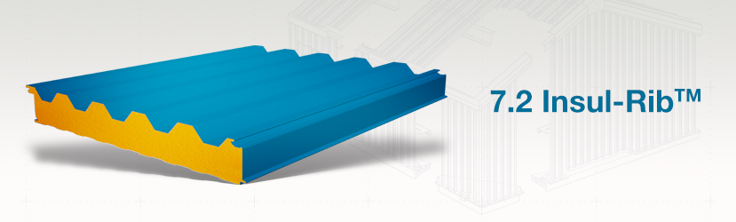
The 7.2 Insul-Rib™ insulated metal wall panel combines a traditional 7.2 rib panel design with a polyurethane foam core. This widely used profile is available as an insulated panel in various thicknesses.
The 7.2 Insul-Rib™ panel has a standard FM Approved Class 1 foam core and offers excellent insulating values. The metal and foam composite construction creates a rigid panel far stronger than the individual parts. This increases the span capability of the panel and reduces the need for secondary structural components.
FM Approved Class 1 with no height restrictions.
Superior Insulating Value across the entire wall and roof area is assured with 7.2 Insul-Rib™ panels. The advanced polyurethane core provides enhanced insulation values that significantly lowers heating and cooling costs.
One-Piece Construction process assures rapid completion of the wall and roof system. Factory fabricated composite panels are attached directly to the supporting structure and multiple steps to construct the insulated wall and roof are eliminated. Faster building completion means reduced construction and interim financing costs.
Lightweight yet Structurally Strong panels weigh only 2 ½ to 3 ½ pounds per square foot, but are structurally strong enough for long spans that can significantly reduce costs for frame support.
Impermeable Faces & Built-in Thermal Breaks ensure the highest insulating values are maintained for the life of the building. Panels are manufactured with impermeable faces and when installed the insulation is completely encapsulated by metal trim that creates an impermeable membrane on all sides of the panel. The aged “R” values are comparable to the initial “R” values many years after the buildings original completion. Assured thermal values mean lower heating and cooling costs.
Class 1 Polyurethane Foam meets the requirements of the major model building codes for many types of construction. Unlike panels with expanded polystyrene cores they will not produce a self-propagating fire. Local building codes may require automatic fire suppression systems for most installations.
Concealed Attachment with clips and fasteners at the side joint of the panel offers a clean high profile appearance. No more barn like metal building looks.
Robertson Buildings are Lightweight, yet very strong and durable attributing to reduced costs for erection and structural support.
| Exterior Profile: | 7.2″ on-center rib pattern, 1-½” deep. | |||
| Interior Profile: | Mesa wave pattern, nominal 1/8″ deep.Light Mesa wave pattern, nominal 1/16″ deep. | |||
| Foam Core: | Foamed-in-place, Non-CFC & zero ODP polyurethane, Factory Mutual Class 1 approval. | |||
| Thermal Values: | R-Values with Air Films | 73° Mean | ||
| 3″ Panel | 12.17 | |||
| 4″ Panel | 18.49 | |||
| 5″ Panel | 25.15 | |||
| 6″ Panel | 31.74 | |||
| • R-Values include the air films on each side of the panel• 73° Mean based on ASTM C1363 Thermal Testing | ||||
| Module Width: | Nominal 36″ | |||
| Panel Thickness: | Nominal overall 3″, 4″, 5″, 6″ (Includes rib height) | |||
| Panel Lengths: | Standard 8′-0″ to 40′-0″. | |||
| Horizontal Application Reveal Widths: | ||||
| Exterior Facings: | Stucco embossed, G-90 galvanized and/or AZ-50 aluminum-zinc coated steel in 26 Ga., 24 Ga. and 22 Ga. | |||
| Interior Facings: | Stucco embossed, G-90 galvanized and/or AZ-50 aluminum-zinc coated steel in 26 Ga., 24 Ga. and 22 Ga. | |||
| Standard Exterior: | Full-Strength 70% PVDF Fluoropolymer Coating. | |||
| Exterior Finishes & Colors: | Siliconized Polyester, Fluropon® Full-Strength 70% PVDF Fluoropolymer Coating.Note: Prices may vary by color, gauge and quantity of metal. | |||
| Interior Finishes & Colors: | USDA-compliant Polyester, Igloo White. USDA-compliant PVC Plastisol White. |
|||
| Joint: | Offset double tongue-and-groove with extended metal shelf for positive face fastening. | |||
| Fastening: | Fastener & Clip concealed in the side joint. | |||
| FM Approved Class 1 with no height restrictions. | ||||
Allowable Uniform Loads for Panels with 26 Gage Facings
| Panel Type | Span Conditions | Design Criteria | Support Span (Feet) | |||||||||||
| 4′ | 5′ | 6′ | 7′ | 8′ | 9′ | 10′ | 11′ | 12′ | 13′ | 14′ | 15′ | |||
| 3″ CF-36 Insul-Rib | Two Spans | Bending & Shear | 101.7 | 69.3 | 51.0 | 39.3 | 31.5 | 25.8 | 21.6 | 18.4 | 15.9 | 13.9 | 12.3 | 10.9 |
| L/180 | 431.8 | 251.8 | 165.5 | 117.6 | 88.0 | 68.4 | 54.6 | 44.5 | 36.9 | 31.0 | 26.3 | 22.5 | ||
| Pattern FP1 | 42.7 | 36.0 | 31.4 | 28.2 | 25.7 | 23.8 | 21.6 | 18.4 | 15.9 | 13.9 | 12.3 | 10.9 | ||
| Pattern FP11 | 101.7 | 69.3 | 51.0 | 39.3 | 31.5 | 25.8 | 21.6 | 18.4 | 15.9 | 13.9 | 12.3 | 10.9 | ||
| Three or More Spans | Bending & Shear | 119.1 | 80.2 | 58.5 | 45.0 | 36.0 | 29.6 | 24.8 | 21.2 | 18.4 | 16.1 | 14.2 | 12.7 | |
| L/180 | 384.1 | 228.7 | 152.2 | 108.7 | 81.4 | 63.1 | 50.2 | 40.7 | 33.6 | 28.0 | 23.6 | 20.1 | ||
| Pattern FP1 | 47.5 | 39.9 | 34.9 | 31.3 | 28.6 | 26.5 | 24.8 | 21.2 | 18.4 | 16.1 | 14.2 | 12.7 | ||
| Pattern FP11 | 116.2 | 80.2 | 58.5 | 45.0 | 36.0 | 29.6 | 24.8 | 21.2 | 18.4 | 16.1 | 14.2 | 12.7 | ||
| 4″ CF-36 Insul-Rib | Two Spans | Bending & Shear | 107.7 | 75.0 | 56.3 | 44.2 | 35.9 | 29.9 | 25.3 | 21.8 | 19.0 | 16.7 | 14.9 | 13.3 |
| L/180 | 466.5 | 280.1 | 189.3 | 138.1 | 106.1 | 84.5 | 69.1 | 57.6 | 48.8 | 41.8 | 36.2 | 31.6 | ||
| Pattern FP1 | 48.1 | 40.0 | 34.4 | 30.4 | 27.4 | 25.0 | 23.0 | 21.5 | 19.0 | 16.7 | 14.9 | 13.3 | ||
| Pattern FP11 | 105.5 | 75.0 | 56.3 | 44.2 | 35.9 | 29.9 | 25.3 | 21.8 | 19.0 | 16.7 | 14.9 | 13.3 | ||
| Three or More Spans | Bending & Shear | 124.5 | 85.3 | 63.2 | 49.3 | 40.0 | 33.2 | 28.2 | 24.3 | 21.3 | 18.8 | 16.7 | 15.0 | |
| L/180 | 423.2 | 260.1 | 178.5 | 131.3 | 101.3 | 80.7 | 65.9 | 54.8 | 46.2 | 39.4 | 33.9 | 29.5 | ||
| Pattern FP1 | 53.2 | 44.0 | 37.8 | 33.4 | 30.1 | 27.5 | 25.4 | 23.7 | 21.3 | 18.8 | 16.7 | 15.0 | ||
| Pattern FP11 | 116.6 | 85.3 | 63.2 | 49.3 | 40.0 | 33.2 | 28.2 | 24.3 | 21.3 | 18.8 | 16.7 | 15.0 | ||
| 5″ CF-36 Insul-Rib | Two Spans | Bending & Shear | 114.8 | 81.4 | 62.0 | 49.3 | 40.5 | 34.0 | 29.0 | 25.2 | 22.1 | 19.5 | 17.4 | 15.7 |
| L/180 | 514.2 | 317.9 | 220.5 | 164.5 | 128.8 | 104.3 | 86.6 | 73.2 | 62.8 | 54.5 | 47.7 | 42.1 | ||
| Pattern FP1 | 48.6 | 40.4 | 34.9 | 30.8 | 27.7 | 25.3 | 23.3 | 21.7 | 20.4 | 18.7 | 17.3 | 15.7 | ||
| Pattern FP11 | 106.6 | 81.4 | 62.0 | 49.3 | 40.5 | 34.0 | 29.0 | 25.2 | 22.1 | 19.5 | 17.4 | 15.7 | ||
| Three or More Spans | Bending & Shear | 131.0 | 91.1 | 68.5 | 54.1 | 44.2 | 37.1 | 31.7 | 27.5 | 24.2 | 21.5 | 19.3 | 17.4 | |
| L/180 | 475.0 | 300.4 | 211.3 | 158.9 | 125.0 | 101.4 | 84.1 | 71.0 | 60.8 | 52.5 | 45.8 | 40.2 | ||
| Pattern FP1 | 53.3 | 44.1 | 37.9 | 33.5 | 30.2 | 27.6 | 25.5 | 23.8 | 22.4 | 20.6 | 19.1 | 17.4 | ||
| Pattern FP11 | 117.0 | 91.1 | 68.5 | 54.1 | 44.2 | 37.1 | 31.7 | 27.5 | 24.2 | 21.5 | 19.3 | 17.4 | ||
| 6″CF-36Insul-Rib | TwoSpans | Bending & Shear | 121.1 | 87.1 | 67.1 | 53.9 | 44.6 | 37.7 | 32.4 | 28.2 | 24.8 | 22.0 | 19.7 | 17.8 |
| L/180 | 559.5 | 353.9 | 250.2 | 189.7 | 150.6 | 123.4 | 103.6 | 88.4 | 76.6 | 67.0 | 59.1 | 52.6 | ||
| Pattern FP1 | 49.0 | 40.8 | 35.3 | 31.2 | 28.0 | 25.6 | 23.6 | 21.9 | 20.6 | 18.9 | 17.5 | 16.3 | ||
| Pattern FP11 | 107.5 | 86.8 | 67.1 | 53.9 | 44.6 | 37.7 | 32.4 | 28.2 | 24.8 | 22.0 | 19.7 | 17.8 | ||
| Three or More Spans | Bending & Shear | 136.8 | 96.4 | 73.1 | 58.3 | 48.0 | 40.5 | 34.8 | 30.3 | 26.8 | 23.9 | 21.5 | 19.4 | |
| L/180 | 523.4 | 338.1 | 242.1 | 185.0 | 147.5 | 121.2 | 101.7 | 86.8 | 75.0 | 65.4 | 57.5 | 51.0 | ||
| Pattern FP1 | 53.5 | 44.3 | 38.1 | 33.6 | 30.3 | 27.7 | 25.6 | 23.8 | 22.4 | 20.7 | 19.2 | 17.9 | ||
| Pattern FP11 | 117.4 | 94.1 | 73.1 | 58.3 | 48.0 | 40.5 | 34.8 | 30.3 | 26.8 | 23.9 | 21.5 | 19.4 | ||
Panel Thickness Includes Rib Height
Notes:
Allowable Uniform Loads for Panels with 24 Gage Exterior/26 Gage Interior Facings
| Panel Type | Span Conditions | Design Criteria | Support Span (Feet) | |||||||||||
| 4′ | 5′ | 6′ | 7′ | 8′ | 9′ | 10′ | 11′ | 12′ | 13′ | 14′ | 15′ | |||
| 3″ CF-36 Insul-Rib | TwoSpans | Bending & Shear | 129.4 | 87.6 | 64.0 | 49.3 | 39.3 | 32.2 | 27.0 | 23.0 | 19.8 | 17.3 | 15.3 | 13.6 |
| L/180 | 534.1 | 304.9 | 196.9 | 137.8 | 102.0 | 78.6 | 62.4 | 50.6 | 41.8 | 35.1 | 29.7 | 25.5 | ||
| Pattern FP1 | 42.5 | 35.8 | 31.4 | 28.1 | 25.7 | 23.7 | 22.2 | 20.9 | 19.8 | 17.3 | 15.3 | 13.6 | ||
| Pattern FP11 | 129.4 | 87.6 | 64.0 | 49.3 | 39.3 | 32.2 | 27.0 | 23.0 | 19.8 | 17.3 | 15.3 | 13.6 | ||
| Three or More Spans | Bending & Shear | 153.2 | 102.4 | 74.2 | 56.8 | 45.2 | 37.1 | 31.1 | 26.5 | 22.9 | 20.0 | 17.7 | 15.8 | |
| L/180 | 467.0 | 272.6 | 178.6 | 126.0 | 93.6 | 72.2 | 57.1 | 46.2 | 38.0 | 31.7 | 26.7 | 22.7 | ||
| Pattern FP1 | 47.4 | 39.9 | 34.9 | 31.3 | 28.6 | 26.5 | 24.8 | 23.4 | 22.2 | 20.0 | 17.7 | 15.8 | ||
| Pattern FP11 | 153.2 | 102.4 | 74.2 | 56.8 | 45.2 | 37.1 | 31.1 | 26.5 | 22.9 | 20.0 | 17.7 | 15.8 | ||
| 4″ CF-36 Insul-Rib | Two Spans | Bending & Shear | 135.6 | 93.5 | 69.6 | 54.5 | 44.2 | 36.7 | 31.1 | 26.8 | 23.3 | 20.5 | 18.3 | 16.4 |
| L/180 | 568.7 | 333.1 | 220.6 | 158.4 | 120.1 | 94.8 | 76.9 | 63.8 | 53.8 | 46.0 | 39.8 | 34.7 | ||
| Pattern FP1 | 47.8 | 39.8 | 34.3 | 30.3 | 27.3 | 24.9 | 23.0 | 21.5 | 20.1 | 18.6 | 17.2 | 16.0 | ||
| Pattern FP11 | 135.6 | 93.5 | 69.6 | 54.5 | 44.2 | 36.7 | 31.1 | 26.8 | 23.3 | 20.5 | 18.3 | 16.4 | ||
| Three or More Spans | Bending & Shear | 158.8 | 107.7 | 79.2 | 61.4 | 49.5 | 41.1 | 34.8 | 30.0 | 26.2 | 23.1 | 20.6 | 18.5 | |
| L/180 | 506.6 | 304.3 | 205.2 | 148.9 | 113.7 | 89.9 | 73.0 | 60.5 | 50.9 | 43.4 | 37.3 | 32.4 | ||
| Pattern FP1 | 53.1 | 43.9 | 37.8 | 33.4 | 30.0 | 27.5 | 25.4 | 23.7 | 22.3 | 20.6 | 19.1 | 17.8 | ||
| Pattern FP11 | 158.8 | 107.7 | 79.2 | 61.4 | 49.5 | 41.1 | 34.8 | 30.0 | 26.2 | 23.1 | 20.6 | 18.5 | ||
| 5″ CF-36 Insul-Rib | Two Spans | Bending & Shear | 143.1 | 100.4 | 75.9 | 60.1 | 49.3 | 41.3 | 35.3 | 30.6 | 26.8 | 23.8 | 21.2 | 19.1 |
| L/180 | 616.6 | 371.1 | 252.0 | 184.9 | 143.0 | 114.8 | 94.7 | 79.7 | 68.1 | 59.0 | 51.6 | 45.5 | ||
| Pattern FP1 | 48.2 | 40.2 | 34.7 | 30.7 | 27.7 | 25.3 | 23.3 | 21.7 | 20.4 | 18.7 | 17.4 | 16.2 | ||
| Pattern FP11 | 143.1 | 100.4 | 75.9 | 60.1 | 49.3 | 41.3 | 35.3 | 30.6 | 26.8 | 23.8 | 21.2 | 19.1 | ||
| Three or More Spans | Bending & Shear | 165.5 | 113.9 | 84.8 | 66.6 | 54.2 | 45.4 | 38.7 | 33.6 | 29.5 | 26.2 | 23.5 | 21.2 | |
| L/180 | 559.5 | 345.4 | 238.5 | 176.9 | 137.8 | 111.0 | 91.6 | 77.1 | 65.8 | 56.8 | 49.5 | 43.4 | ||
| Pattern FP1 | 53.2 | 44.1 | 37.9 | 33.5 | 30.2 | 27.6 | 25.5 | 23.8 | 22.4 | 20.6 | 19.1 | 17.9 | ||
| Pattern FP11 | 162.8 | 113.9 | 84.8 | 66.6 | 54.2 | 45.4 | 38.7 | 33.6 | 29.5 | 26.2 | 23.5 | 21.2 | ||
| 6″ CF-36 Insul-Rib | Two Spans | Bending & Shear | 149.8 | 106.5 | 81.4 | 65.2 | 53.8 | 45.4 | 39.0 | 34.0 | 30.0 | 26.6 | 23.9 | 21.6 |
| L/180 | 662.0 | 407.2 | 281.9 | 210.3 | 165.0 | 134.1 | 111.9 | 95.1 | 82.1 | 71.7 | 63.2 | 56.1 | ||
| Pattern FP1 | 48.6 | 40.5 | 35.1 | 31.0 | 28.0 | 25.5 | 23.6 | 21.9 | 20.6 | 18.9 | 17.5 | 16.3 | ||
| Pattern FP11 | 148.6 | 106.5 | 81.4 | 65.2 | 53.8 | 45.4 | 39.0 | 34.0 | 30.0 | 26.6 | 23.9 | 21.6 | ||
| Three or More Spans | Bending & Shear | 171.6 | 119.5 | 89.9 | 71.2 | 58.4 | 49.2 | 42.2 | 36.8 | 32.4 | 28.9 | 26.0 | 23.5 | |
| L/180 | 608.8 | 383.8 | 269.9 | 203.4 | 160.6 | 131.0 | 109.4 | 93.1 | 80.2 | 69.9 | 61.5 | 54.4 | ||
| Pattern FP1 | 53.4 | 44.2 | 38.0 | 33.6 | 30.3 | 27.6 | 25.6 | 23.8 | 22.4 | 20.7 | 19.2 | 17.9 | ||
| Pattern FP11 | 163.2 | 119.5 | 89.9 | 71.2 | 58.4 | 49.2 | 42.2 | 36.8 | 32.4 | 28.9 | 26.0 | 23.5 | ||
Panel Thickness Includes Rib Height
Notes:
Allowable Uniform Loads for Panels with 24 Gage Exterior/26 Gage Interior Facings
| Panel Type | Span Conditions | Design Criteria | Support Span (Feet) | |||||||||||
| 4′ | 5′ | 6′ | 7′ | 8′ | 9′ | 10′ | 11′ | 12′ | 13′ | 14′ | 15′ | |||
| 3″ CF-36 Insul-Rib | Two Spans | Bending & Shear | 147.5 | 99.4 | 72.4 | 55.6 | 44.3 | 36.3 | 30.3 | 25.8 | 22.3 | 19.5 | 17.1 | 15.2 |
| L/180 | 601.4 | 339.6 | 217.2 | 150.9 | 111.0 | 85.1 | 67.2 | 54.4 | 44.9 | 37.5 | 31.8 | 27.2 | ||
| Pattern FP1 | 42.4 | 35.8 | 31.3 | 28.1 | 25.6 | 23.7 | 22.2 | 20.9 | 19.9 | 18.3 | 17.0 | 15.2 | ||
| Pattern FP11 | 147.5 | 99.4 | 72.4 | 55.6 | 44.3 | 36.3 | 30.3 | 25.8 | 22.3 | 19.5 | 17.1 | 15.2 | ||
| Three or More Spans | Bending & Shear | 175.5 | 116.8 | 84.4 | 64.4 | 51.2 | 41.9 | 35.0 | 29.8 | 25.8 | 22.6 | 19.9 | 17.7 | |
| L/180 | 521.0 | 300.9 | 195.5 | 137.0 | 101.3 | 77.7 | 61.4 | 49.5 | 40.7 | 33.8 | 28.5 | 24.3 | ||
| Pattern FP1 | 47.4 | 39.9 | 34.9 | 31.3 | 28.6 | 26.4 | 24.8 | 23.4 | 22.2 | 20.5 | 19.0 | 17.7 | ||
| Pattern FP11 | 175.5 | 116.8 | 84.4 | 64.4 | 51.2 | 41.9 | 35.0 | 29.8 | 25.8 | 22.6 | 19.9 | 17.7 | ||
| 4″ CF-36 Insul-Rib | Two Spans | Bending & Shear | 153.8 | 105.4 | 78.2 | 61.0 | 49.3 | 41.0 | 34.7 | 29.8 | 26.0 | 22.9 | 20.3 | 18.2 |
| L/180 | 635.9 | 367.8 | 241.0 | 171.5 | 129.1 | 101.3 | 81.8 | 67.6 | 56.9 | 48.6 | 41.9 | 36.5 | ||
| Pattern FP1 | 47.7 | 39.6 | 34.2 | 30.3 | 27.3 | 24.9 | 23.0 | 21.4 | 20.1 | 18.6 | 17.2 | 16.0 | ||
| Pattern FP11 | 153.8 | 105.4 | 78.2 | 61.0 | 49.3 | 41.0 | 34.7 | 29.8 | 26.0 | 22.9 | 20.3 | 18.2 | ||
| Three or More Spans | Bending & Shear | 181.2 | 122.2 | 89.5 | 69.2 | 55.6 | 46.0 | 38.9 | 33.5 | 29.2 | 25.8 | 23.0 | 20.6 | |
| L/180 | 560.9 | 332.9 | 222.3 | 160.1 | 121.5 | 95.7 | 77.4 | 64.0 | 53.7 | 45.7 | 39.3 | 34.1 | ||
| Pattern FP1 | 53.0 | 43.9 | 37.7 | 33.3 | 30.0 | 27.5 | 25.4 | 23.7 | 22.3 | 20.6 | 19.1 | 17.8 | ||
| Pattern FP11 | 181.2 | 122.2 | 89.5 | 69.2 | 55.6 | 46.0 | 38.9 | 33.5 | 29.2 | 25.8 | 23.0 | 20.6 | ||
| 5″ CF-36 Insul-Rib | Two Spans | Bending & Shear | 161.4 | 112.5 | 84.7 | 66.9 | 54.7 | 45.8 | 39.1 | 33.9 | 29.7 | 26.3 | 23.5 | 21.2 |
| L/180 | 683.8 | 405.9 | 272.4 | 198.1 | 152.1 | 121.4 | 99.7 | 83.6 | 71.3 | 61.6 | 53.8 | 47.4 | ||
| Pattern FP1 | 48.1 | 40.0 | 34.6 | 30.6 | 27.6 | 25.2 | 23.3 | 21.7 | 20.4 | 18.7 | 17.4 | 16.2 | ||
| Pattern FP11 | 161.4 | 112.5 | 84.7 | 66.9 | 54.7 | 45.8 | 39.1 | 33.9 | 29.7 | 26.3 | 23.5 | 21.2 | ||
| Three or More Spans | Bending & Shear | 188.0 | 128.6 | 95.3 | 74.6 | 60.6 | 50.6 | 43.1 | 37.3 | 32.8 | 29.1 | 26.0 | 23.5 | |
| L/180 | 614.4 | 374.4 | 256.0 | 188.4 | 145.8 | 116.9 | 96.2 | 80.7 | 68.7 | 59.3 | 51.6 | 45.3 | ||
| Pattern FP1 | 53.2 | 44.0 | 37.9 | 33.5 | 30.1 | 27.6 | 25.5 | 23.8 | 22.4 | 20.6 | 19.1 | 17.9 | ||
| Pattern FP11 | 188.0 | 128.6 | 95.3 | 74.6 | 60.6 | 50.6 | 43.1 | 37.3 | 32.8 | 29.1 | 26.0 | 23.5 | ||
| 6″ CF-36 Insul-Rib | Two Spans | Bending & Shear | 168.3 | 118.8 | 90.4 | 72.2 | 59.5 | 50.2 | 43.1 | 37.6 | 33.1 | 29.4 | 26.4 | 23.8 |
| L/180 | 729.4 | 442.1 | 302.4 | 223.6 | 174.2 | 140.8 | 117.0 | 99.1 | 85.4 | 74.4 | 65.5 | 58.1 | ||
| Pattern FP1 | 48.4 | 40.4 | 34.9 | 30.9 | 27.9 | 25.5 | 23.5 | 21.9 | 20.6 | 18.9 | 17.5 | 16.3 | ||
| Pattern FP11 | 168.3 | 118.8 | 90.4 | 72.2 | 59.5 | 50.2 | 43.1 | 37.6 | 33.1 | 29.4 | 26.4 | 23.8 | ||
| Three or More Spans | Bending & Shear | 194.3 | 134.4 | 100.6 | 79.4 | 65.0 | 54.6 | 46.8 | 40.8 | 35.9 | 32.0 | 28.8 | 26.0 | |
| L/180 | 664.3 | 413.2 | 287.6 | 215.0 | 168.8 | 137.1 | 114.1 | 96.8 | 83.3 | 72.5 | 63.7 | 56.4 | ||
| Pattern FP1 | 53.3 | 44.1 | 38.0 | 33.6 | 30.2 | 27.6 | 25.6 | 23.8 | 22.4 | 20.7 | 19.2 | 17.9 | ||
| Pattern FP11 | 194.3 | 134.4 | 100.6 | 79.4 | 65.0 | 54.6 | 46.8 | 40.8 | 35.9 | 32.0 | 28.8 | 26.0 | ||
Panel Thickness Includes Rib Height
Notes: