Contact Us: 800-387-5335
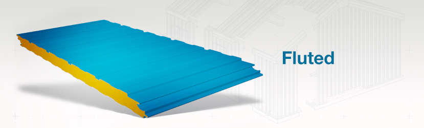
CF Fluted wall panel provides bold vertical lines complimentary to almost any commercial or industrial building. Inverted ribs in the profile enhance the high-tech industrial look. The CF Fluted wall panel is the recommended profile for the exterior of cold storage buildings.
In new and retrofit construction, the panels function as walls, ceilings and roofing for cooler, freezer and food processing buildings. They are ideally suited for:
Cold Storage
| Exterior Profile: | Flutes 1″ wide and nominal 3/8″ deep | |||
| Interior Profile: | Mesa wave pattern, nominal 1/8″ deep. | |||
| Foam Core: | Foamed-in-place, Non-CFC & zero ODP polyurethane, Factory Mutual Class 1 approval. | |||
| Thermal Values: | R-Values with Air Films | 75° Mean | 40° Mean | |
| 2″ Panel | 15.14 | 17.03 | ||
| 2-1/2″ Panel | 18.71 | 21.29 | ||
| 2-3/4″ Panel | 20.49 | 23.42 | ||
| 3″ Panel | 22.27 | 25.55 | ||
| 4″ Panel | 29.42 | 34.06 | ||
| 5″ Panel | 36.56 | 42.58 | ||
| 6″ Panel | 43.71 | 51.09 | ||
| • R-Values include the air films on each side of the panel.• 75° Mean based on ASTM C518 Thermal Testing. 40° Mean based on ASTM C1363 Thermal Testing (Values for C1363 based on 4″ panel testing). All values for other thicknesses extrapolated. | ||||
| Module Width: | 30″, 36″ & 42″ | |||
| Panel Thickness: | 2”, 2-½”, 2-¾” , 3” & 4” (4” panel only available from Mattoon and Jackson facilities) |
|||
| Panel Lengths: | Standard 8’-0” to 40’-0” for 30” and 36” widths. Standard 8’-0” to 32’-0” for 42” width. |
|||
| Horizontal Application Reveal Widths: |
1/4″, 1/2″, 3/4″ & 1 | |||
| Exterior Facings: | Stucco embossed, G-90 galvanized and/or AZ-50 aluminum-zinc coated steel in 24 Ga. and 22 Ga. | |||
| Interior Facings: | Stucco embossed, G-90 galvanized and/or AZ-50 aluminum-zinc coated steel in 26 Ga., 24 Ga. and 22 Ga. | |||
| Standard Exterior: | Full-Strength 70% PVDF Fluoropolymer Coating. | |||
| Exterior Finishes & Colors: | Siliconized Polyester, Fluropon® Full-Strength 70% PVDF Fluoropolymer Coating.Note: Prices may vary by color, gauge and quantity of metal. | |||
| Interior Finishes & Colors: | USDA-compliant Polyester, Igloo White. | |||
| Joint: | Offset double tongue-and-groove with extended metal shelf for positive face fastening. | |||
| Fastening: | Fastener & Clip concealed in the side joint. | |||
| FM Approved Class 1 with no height restrictions | ||||
| CF-42 FLUTED WALL PANEL | |||||||||||||
| PANEL WIDTH |
SPAN CONDITION |
FASTENING PATTERN |
ALLOWABLE CONNECTION LOAD (PSF) | ||||||||||
| Panel Span (ft) | |||||||||||||
| 5 | 6 | 7 | 8 | 9 | 10 | 11 | 12 | 13 | 14 | 15 | |||
| 2″ Thick | Two Spans | Pattern FP1 | 31.6 | 25.8 | 21.7 | 18.8 | 16.5 | 14.8 | 13.3 | 12.2 | 11.2 | 10.3 | 9.6 |
| Pattern FP2 | 46.2 | 37.7 | 31.8 | 27.5 | 24.2 | 21.6 | 19.5 | 17.8 | 16.4 | 14.3 | 12.5 | ||
| Pattern FP3 | 58.3 | 47.6 | 40.2 | 34.7 | 30.5 | 26.0 | 22.1 | 19.0 | 16.4 | 14.3 | 12.5 | ||
| Three Or More Spans |
Pattern FP1 | 89.2 | 73.0 | 62.2 | 54.5 | 48.6 | 43.9 | 40.1 | 36.9 | 33.2 | 36.9 | 33.2 | |
| Pattern FP2 | 89.2 | 73.0 | 62.2 | 54.5 | 48.6 | 43.9 | 40.1 | 36.9 | 33.2 | 36.9 | 33.2 | ||
| Pattern FP3 | 89.2 | 73.0 | 62.2 | 54.5 | 48.6 | 43.9 | 40.1 | 36.9 | 33.2 | 36.9 | 33.2 | ||
| 2.5″ Thick | Two Spans | Pattern FP1 | 33.3 | 27.2 | 22.9 | 19.8 | 17.4 | 15.5 | 14.0 | 12.7 | 11.7 | 10.8 | 10.1 |
| Pattern FP2 | 47.5 | 38.8 | 32.7 | 28.2 | 24.8 | 22.1 | 19.9 | 18.2 | 16.7 | 15.4 | 14.3 | ||
| Pattern FP3 | 60.1 | 49.0 | 41.3 | 35.7 | 31.4 | 28.0 | 25.2 | 23.0 | 21.1 | 19.5 | 17.3 | ||
| Three Or More Spans |
Pattern FP1 | 34.6 | 28.6 | 24.4 | 21.3 | 18.8 | 16.9 | 15.3 | 14.0 | 12.9 | 12.0 | 11.2 | |
| Pattern FP2 | 49.3 | 40.8 | 34.8 | 30.3 | 26.8 | 24.1 | 21.9 | 20.0 | 18.4 | 17.1 | 16.0 | ||
| Pattern FP3 | 62.4 | 51.6 | 44.0 | 38.3 | 33.9 | 30.5 | 27.7 | 24.7 | 21.3 | 18.5 | 16.2 | ||
| 3″ Thick | Two Spans | Pattern FP1 | 35.1 | 28.7 | 24.1 | 20.8 | 18.3 | 16.3 | 14.7 | 13.4 | 12.2 | 11.3 | 10.5 |
| Pattern FP2 | 48.8 | 39.8 | 33.6 | 28.9 | 25.4 | 22.6 | 20.4 | 18.6 | 17.0 | 15.7 | 14.6 | ||
| Pattern FP3 | 61.8 | 50.5 | 42.5 | 36.7 | 32.2 | 28.7 | 25.9 | 23.5 | 21.6 | 20.0 | 18.6 | ||
| Pattern FP4 | 71.1 | 58.0 | 48.9 | 42.2 | 37.0 | 33.0 | 29.7 | 27.1 | 24.8 | 22.9 | 21.3 | ||
| Three Or More Spans |
Pattern FP1 | 36.1 | 29.9 | 25.4 | 22.2 | 19.6 | 17.6 | 16.0 | 14.6 | 13.5 | 12.5 | 11.6 | |
| Pattern FP2 | 50.2 | 41.5 | 35.4 | 30.8 | 27.3 | 24.5 | 22.2 | 20.3 | 18.7 | 17.4 | 16.2 | ||
| Pattern FP3 | 63.7 | 52.6 | 44.8 | 39.0 | 34.6 | 31.0 | 28.2 | 25.8 | 23.7 | 22.0 | 20.5 | ||
| Pattern FP4 | 73.2 | 60.5 | 51.5 | 44.9 | 39.7 | 35.7 | 32.4 | 29.6 | 27.2 | 23.8 | 21.0 | ||
| 4″ Thick | Two Spans | Pattern FP1 | 43.0 | 35.3 | 29.8 | 25.6 | 22.5 | 20.0 | 18.0 | 16.4 | 15.0 | 13.8 | 12.8 |
| Pattern FP2 | 63.0 | 51.8 | 43.6 | 37.6 | 33.0 | 29.3 | 26.4 | 24.0 | 22.0 | 20.3 | 18.8 | ||
| Pattern FP3 | 74.3 | 61.0 | 51.5 | 44.3 | 38.9 | 34.6 | 31.2 | 28.3 | 26.0 | 23.9 | 22.2 | ||
| Pattern FP4 | 79.6 | 65.4 | 55.1 | 47.5 | 41.7 | 37.1 | 33.4 | 30.3 | 27.8 | 25.7 | 23.8 | ||
| Pattern FP5 | 83.3 | 68.4 | 57.7 | 49.7 | 43.6 | 38.8 | 34.9 | 31.7 | 29.1 | 26.8 | 24.9 | ||
| Pattern FP9 | 89.5 | 73.5 | 62.0 | 53.4 | 46.9 | 41.7 | 37.5 | 34.1 | 31.3 | 28.8 | 26.8 | ||
| Pattern FP10 | 93.6 | 76.9 | 64.8 | 55.9 | 49.0 | 43.6 | 39.3 | 35.7 | 32.7 | 30.2 | 28.0 | ||
| Three Or More Spans |
Pattern FP1 | 44.0 | 36.3 | 30.9 | 26.9 | 23.8 | 21.3 | 19.3 | 17.7 | 16.3 | 15.1 | 14.1 | |
| Pattern FP2 | 64.4 | 53.2 | 45.3 | 39.4 | 34.9 | 31.3 | 28.3 | 25.9 | 23.9 | 22.1 | 20.6 | ||
| Pattern FP3 | 76.0 | 62.8 | 53.4 | 46.5 | 41.1 | 36.9 | 33.4 | 30.6 | 28.2 | 26.1 | 24.3 | ||
| Pattern FP4 | 81.4 | 67.2 | 57.2 | 49.8 | 44.1 | 39.5 | 35.8 | 32.8 | 30.2 | 28.0 | 26.1 | ||
| Pattern FP5 | 85.1 | 70.3 | 59.9 | 52.1 | 46.1 | 41.3 | 37.5 | 34.3 | 31.6 | 29.3 | 27.3 | ||
| Pattern FP9 | 91.5 | 75.6 | 64.2 | 55.6 | 49.0 | 43.8 | 39.6 | 36.2 | 33.3 | 30.8 | 28.7 | ||
| Pattern FP10 | 92.6 | 75.9 | 64.2 | 55.6 | 49.0 | 43.8 | 39.6 | 36.2 | 33.3 | 30.8 | 28.7 | ||
| 5″ Thick | Two Spans | Pattern FP1 | 42.3 | 35.8 | 30.3 | 26.2 | 23.0 | 20.4 | 18.4 | 16.7 | 15.3 | 14.1 | 13.0 |
| Pattern FP2 | 61.9 | 52.5 | 44.5 | 38.4 | 33.6 | 29.9 | 26.9 | 24.4 | 22.4 | 20.6 | 19.1 | ||
| Pattern FP3 | 73.1 | 62.0 | 52.5 | 45.2 | 39.7 | 35.3 | 31.7 | 28.8 | 26.4 | 24.3 | 22.6 | ||
| Pattern FP4 | 78.2 | 66.4 | 56.2 | 48.5 | 42.5 | 37.8 | 34.0 | 30.9 | 28.3 | 26.1 | 24.2 | ||
| Pattern FP5 | 81.9 | 69.4 | 58.8 | 50.7 | 44.5 | 39.6 | 35.6 | 32.3 | 29.6 | 27.3 | 25.3 | ||
| Pattern FP9 | 88.0 | 74.6 | 63.2 | 54.5 | 47.8 | 42.5 | 38.2 | 34.7 | 31.8 | 29.3 | 27.2 | ||
| Pattern FP10 | 92.0 | 78.1 | 66.1 | 57.0 | 50.0 | 44.5 | 40.0 | 36.3 | 33.3 | 30.7 | 28.4 | ||
| Three Or More Spans |
Pattern FP1 | 43.5 | 36.6 | 31.2 | 27.1 | 24.0 | 21.5 | 19.4 | 17.8 | 16.4 | 15.2 | 14.1 | |
| Pattern FP2 | 63.8 | 53.7 | 45.7 | 39.7 | 35.1 | 31.5 | 28.5 | 26.1 | 24.0 | 22.2 | 20.7 | ||
| Pattern FP3 | 75.2 | 63.3 | 53.9 | 46.8 | 41.4 | 37.1 | 33.6 | 30.7 | 28.3 | 26.2 | 24.4 | ||
| Pattern FP4 | 80.6 | 67.8 | 57.7 | 50.2 | 44.4 | 39.8 | 36.0 | 32.9 | 30.3 | 28.1 | 26.2 | ||
| Pattern FP5 | 84.3 | 70.9 | 60.4 | 52.5 | 46.4 | 41.6 | 37.7 | 34.4 | 31.7 | 29.4 | 27.4 | ||
| Pattern FP9 | 90.6 | 76.2 | 64.9 | 56.4 | 49.9 | 44.7 | 40.5 | 30.7 | 34.1 | 31.6 | 29.4 | ||
| Pattern FP10 | 94.8 | 79.8 | 67.9 | 59.0 | 52.2 | 46.8 | 42.4 | 38.7 | 35.7 | 33.0 | 30.8 | ||
| 6″ Thick | Two Spans | Pattern FP1 | 41.7 | 35.3 | 30.7 | 26.6 | 23.4 | 20.8 | 18.7 | 17.0 | 15.5 | 14.3 | 13.2 |
| Pattern FP2 | 61.2 | 51.7 | 45.0 | 39.0 | 34.3 | 30.5 | 27.4 | 24.9 | 22.8 | 21.0 | 19.4 | ||
| Pattern FP3 | 72.1 | 61.0 | 53.0 | 46.0 | 40.4 | 36.0 | 32.3 | 29.4 | 26.9 | 24.7 | 22.9 | ||
| Pattern FP4 | 77.2 | 65.3 | 56.8 | 49.3 | 43.3 | 38.5 | 34.6 | 31.4 | 28.8 | 26.5 | 24.5 | ||
| Pattern FP5 | 80.8 | 68.3 | 59.4 | 51.6 | 45.3 | 40.3 | 36.2 | 32.9 | 30.1 | 27.7 | 25.7 | ||
| Pattern FP9 | 86.9 | 73.4 | 63.9 | 55.5 | 48.7 | 43.3 | 39.0 | 35.4 | 32.3 | 29.8 | 27.6 | ||
| Pattern FP10 | 90.9 | 76.8 | 66.8 | 58.0 | 50.9 | 45.3 | 40.7 | 37.0 | 33.8 | 31.2 | 28.9 | ||
| Three Or More Spans |
Pattern FP1 | 42.8 | 36.3 | 31.4 | 27.3 | 24.1 | 21.6 | 19.6 | 17.9 | 16.4 | 15.2 | 14.2 | |
| Pattern FP2 | 62.7 | 53.2 | 46.0 | 40.0 | 35.4 | 31.7 | 28.7 | 26.2 | 24.1 | 22.3 | 20.8 | ||
| Pattern FP3 | 74.0 | 62.8 | 54.3 | 47.2 | 41.7 | 37.4 | 33.8 | 30.9 | 28.4 | 26.3 | 24.5 | ||
| Pattern FP4 | 79.3 | 67.2 | 58.1 | 50.5 | 44.7 | 40.0 | 36.2 | 33.1 | 30.5 | 28.2 | 26.3 | ||
| Pattern FP5 | 82.9 | 70.3 | 60.8 | 52.9 | 46.7 | 41.9 | 37.9 | 34.6 | 31.9 | 29.5 | 27.5 | ||
| Pattern FP9 | 89.1 | 75.6 | 65.4 | 56.8 | 50.2 | 45.0 | 40.8 | 37.2 | 34.3 | 31.7 | 29.6 | ||
| Pattern FP10 | 93.2 | 79.1 | 68.4 | 59.5 | 52.6 | 47.1 | 42.6 | 38.9 | 35.8 | 33.2 | 30.9 | ||
| CF-42 FLUTED WALL PANEL | |||||||||||||
| PANEL THICKNESS |
SPAN CONDITION |
DESIGN CRITERIA | ALLOWABLE POSITIVE LOAD (PSF) | ||||||||||
| Panel Span (ft) | |||||||||||||
| 5 | 6 | 7 | 8 | 9 | 10 | 11 | 12 | 13 | 14 | 15 | |||
| 2″ Thick | Two Spans | Bending & Shear | 67.6 | 55.2 | 46.6 | 40.2 | 35.4 | 31.6 | 28.6 | 24.4 | 20.3 | 17.2 | 14.7 |
| Deflection (L/180) | 68.9 | 54.3 | 44.0 | 36.3 | 30.3 | 25.6 | 21.9 | 18.8 | 16.3 | 14.2 | 12.4 | ||
| Three Or More Spans |
Bending & Shear | 66.4 | 54.7 | 46.5 | 40.4 | 35.8 | 32.1 | 29.1 | 26.6 | 23.4 | 20.0 | 17.3 | |
| Deflection (L/180) | 69.7 | 54.8 | 44.0 | 36.0 | 29.8 | 24.9 | 21.0 | 17.8 | 15.2 | 13.1 | 11.3 | ||
| 2.5″ Thick | Two Spans | Bending & Shear | 78.4 | 64.0 | 53.9 | 46.5 | 40.9 | 36.5 | 32.9 | 30.0 | 26.9 | 22.6 | 19.3 |
| Deflection (L/180) | 86.9 | 69.1 | 56.4 | 47.0 | 39.7 | 33.9 | 29.2 | 25.4 | 22.2 | 19.5 | 17.2 | ||
| Three Or More Spans |
Bending & Shear | 76.7 | 63.0 | 53.5 | 46.4 | 41.0 | 36.8 | 33.3 | 30.5 | 28.0 | 25.7 | 22.2 | |
| Deflection (L/180) | 87.9 | 69.9 | 56.9 | 47.1 | 39.5 | 33.5 | 28.6 | 24.5 | 21.2 | 18.4 | 16.1 | ||
| 3″ Thick | Two Spans | Bending & Shear | 88.1 | 72.0 | 60.6 | 52.3 | 45.9 | 40.9 | 36.9 | 33.6 | 30.8 | 26.6 | 22.6 |
| Deflection (L/180) | 103.2 | 82.6 | 67.9 | 56.9 | 48.4 | 41.7 | 36.2 | 31.7 | 27.9 | 24.7 | 21.9 | ||
| Three Or More Spans |
Bending & Shear | 86.0 | 70.6 | 59.8 | 51.9 | 45.8 | 41.0 | 37.1 | 33.9 | 31.2 | 28.9 | 25.4 | |
| Deflection (L/180) | 104.2 | 83.5 | 68.6 | 57.4 | 48.6 | 41.5 | 35.8 | 31.0 | 27.1 | 23.7 | 20.9 | ||
| 4″ Thick | Two Spans | Bending & Shear | 94.4 | 77.3 | 65.1 | 56.2 | 49.3 | 43.8 | 39.5 | 35.9 | 32.9 | 30.3 | 28.1 |
| Deflection (L/180) | 129.9 | 104.9 | 87.1 | 73.7 | 63.3 | 55.0 | 48.2 | 42.7 | 37.9 | 33.9 | 30.5 | ||
| Three Or More Spans |
Bending & Shear | 92.0 | 75.4 | 63.8 | 55.2 | 48.7 | 43.5 | 39.3 | 35.9 | 33.0 | 30.6 | 28.5 | |
| Deflection (L/180) | 130.8 | 106.0 | 88.0 | 74.5 | 63.9 | 55.4 | 48.4 | 42.6 | 37.7 | 33.5 | 29.9 | ||
| 5″ Thick | Two Spans | Bending & Shear | 108.2 | 88.8 | 75.0 | 64.7 | 56.7 | 50.5 | 45.5 | 41.2 | 37.7 | 34.8 | 32.3 |
| Deflection (L/180) | 148.4 | 120.7 | 100.8 | 85.8 | 74.2 | 64.9 | 57.4 | 51.1 | 45.7 | 41.2 | 37.3 | ||
| Three Or More Spans |
Bending & Shear | 105.5 | 86.5 | 73.1 | 63.2 | 55.7 | 49.7 | 44.9 | 40.9 | 37.6 | 34.8 | 32.4 | |
| Deflection (L/180) | 149.1 | 121.5 | 101.7 | 86.8 | 75.1 | 65.6 | 57.9 | 51.4 | 45.9 | 41.2 | 37.1 | ||
| 6″ Thick | Two Spans | Bending & Shear | 120.7 | 99.3 | 84.0 | 72.5 | 63.7 | 56.7 | 51.0 | 46.3 | 42.3 | 39.0 | 36.1 |
| Deflection (L/180) | 158.3 | 129.4 | 108.7 | 93.0 | 80.9 | 71.1 | 63.1 | 56.5 | 50.9 | 46.1 | 41.9 | ||
| Three Or More Spans |
Bending & Shear | 117.9 | 96.8 | 81.8 | 70.7 | 62.2 | 55.5 | 50.0 | 45.6 | 41.8 | 38.7 | 36.0 | |
| Deflection (L/180) | 158.8 | 130.1 | 109.4 | 93.9 | 81.7 | 71.9 | 63.8 | 57.1 | 51.4 | 46.4 | 42.2 | ||