Contact Us: 800-387-5335
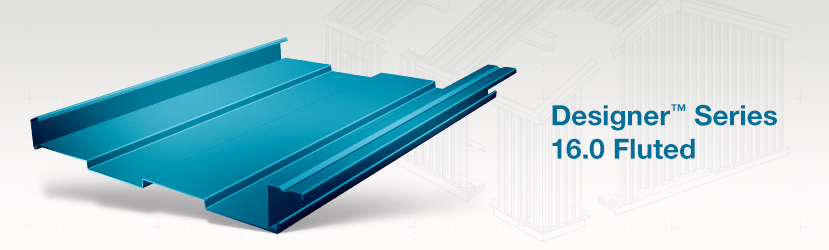
The Designer™ Series panels provide the toughness of metal while creating an attractive, flexible and functional wall or fascia panel. The Designer™ Series is offered in fluted and flat panels, which are equally effective for new construction or retrofitting existing buildings.If your design calls for a smooth or flat wall or fascia, look to the Designer™ Series 12.0 Flat Panel. The Designer™ Series 12.0 Flat Panel offers a 1 ¾-inch deep leg providing the perfect cavity for rigid board insulation.The Designer™ Series 16.0 Fluted Panel offers a continuous rib design with a hidden sidelap where the panels join together. Ribs are 4-inches wide and 3/8-inches deep, providing interesting shadow lines along the length of the wall. The panel legs are 1 ¾-inch deep allowing ample space for rigid board, blanket or batt insulation in the cavity.
Each panel features concealed fastened systems enhancing the appearance. One leg of the panel is attached to the structural using a concealed clip and the other leg snaps securely into the adjoining panel to lock them into position.
Designer™ Series 16″ Fluted 22 Gauge – Negative Design Loads
| 22 GAUGE | |||||||||
| SPAN TYPE | 3.00 | 3.50 | 4.00 | 4.50 | 5.00 | 5.50 | 6.00 | 6.50 | 7.00 |
| 1592 LOAD | 140.40 | 127.24 | 115.05 | 103.84 | 93.60 | 84.34 | 76.05 | 68.74 | 62.40 |
| DESIGN LOAD | 81.16 | 73.55 | 66.50 | 60.02 | 54.10 | 48.75 | 43.96 | 39.73 | 36.07 |
Designer™ Series 16″ Fluted – Section Properties
| NEGATIVE BENDING | POSITIVE BENDING | |||||||
| Panel Gauge |
FY (KSI) |
WEIGHT (PSF) |
Ixe (IN.4/FT.) |
Sxe (IN.3/FT.) |
Maxo (KIP-IN.) |
Ixe (IN.4/FT.) |
Sxe (IN.3/FT.) |
Maxo (KIP-IN.) |
| 24 | 50 | 1.85 | 0.0931 | 0.1516 | 4.5395 | 0.0931 | 0.0667 | 1.9982 |
| 22 | 50 | 2.23 | 0.1258 | 0.2204 | 6.5995 | 0.1251 | 0.0900 | 2.6747 |
Allowable Uniform Loads In Pounds Per Square Foot – 16″ Designer™ Series Flat

| 24 Gauge (Fy = 50 Ksi) | ||||||||
| SPAN TYPE | LOAD TYPE | SPAN IN FEET | ||||||
| 3.0 | 4.0 | 5.0 | 6.0 | 7.0 | 8.0 | 9.0 | ||
| SINGLE | POSITIVE WIND LOAD | 113.5 | 83.3 | 53.3 | 37.0 | 23.7 | 15.9 | 11.2 |
| 2-SPAN | POSITIVE WIND LOAD | 90.0 | 67.5 | 52.6 | 36.7 | 27.0 | 20.7 | 16.4 |
| 3-SPAN | POSITIVE WIND LOAD | 102.3 | 76.7 | 61.4 | 45.7 | 33.7 | 25.8 | 20.4 |
| 4-SPAN | POSITIVE WIND LOAD | 98.5 | 73.9 | 59.1 | 42.7 | 31.5 | 24.1 | 19.1 |
| 22 Gauge (Fy = 50 Ksi ) | ||||||||
| SPAN TYPE | LOAD TYPE | SPAN IN FEET | ||||||
| 3.0 | 4.0 | 5.0 | 6.0 | 7.0 | 8.0 | 9.0 | ||
| SINGLE | POSITIVE WIND LOAD | 198.1 | 111.4 | 71.3 | 49.5 | 31.9 | 21.4 | 15.0 |
| 2-SPAN | POSITIVE WIND LOAD | 149.5 | 110.0 | 70.7 | 49.2 | 36.2 | 27.8 | 22.0 |
| 3-SPAN | POSITIVE WIND LOAD | 169.8 | 127.4 | 88.1 | 61.4 | 45.2 | 34.7 | 27.4 |
| 4-SPAN | POSITIVE WIND LOAD | 163.4 | 122.6 | 82.4 | 57.4 | 42.2 | 32.4 | 25.6 |