Contact Us: 800-387-5335
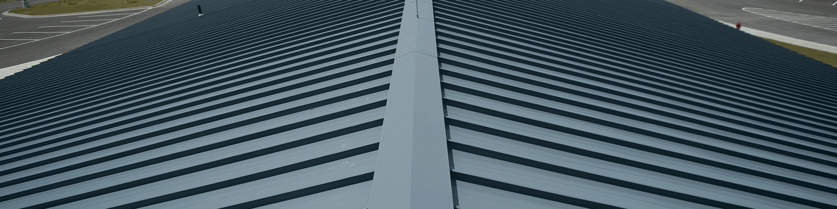
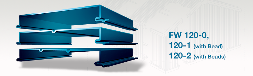
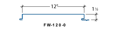
The FW-120 panel is a concealed fastener wall and liner panel that provides a flat appearance. FW-120 is commonly used for architectural, commercial and industrial markets. The heavy gauge offering provides for large spanning capabilities, particularly in composite wall applications. FW-120 is available in a flat profile with one bead or two beads.
Air Infiltration and Water Penetration
The FW-120 Panel has been tested by a certified independent laboratory in accordance with ASTM test procedures for Air Infiltration and Water Penetration at the sidelap. Test results show no air leakage at 1.57PSF and no water penetration at 6.24PSF differential pressure.
FW-120 22 Gauge Negative Design Loads
| 22 GAUGE | ||||||||||
| SPAN TYPE | 3.00 | 3.50 | 4.00 | 5.00 | 5.50 | 5.50 | 6.00 | 6.50 | 7.00 | |
| 1592 LOAD | 171.60 | 152.10 | 132.60 | 113.10 | 93.60 | 87.54 | 81.47 | 75.40 | 69.33 | |
| DESIGN LOAD | 98.62 | 87.41 | 76.21 | 65.00 | 53.79 | 50.31 | 46.82 | 43.33 | 39.84 | |
FW-120 24 Gauge Negative Design Loads
| 24 GAUGE | ||||||||||
| SPAN TYPE | 3.00 | 3.50 | 4.00 | 5.00 | 5.50 | 5.50 | 6.00 | 6.50 | 7.00 | |
| 1592 LOAD | 110.93 | 99.23 | 87.53 | 75.83 | 64.13 | 58.50 | 52.87 | 47.24 | 41.60 | |
| DESIGN LOAD | 63.75 | 57.03 | 50.30 | 43.58 | 36.86 | 33.62 | 30.39 | 27.15 | 23.91 | |
FW-120 – Section Properties
| NEGATIVE BENDING | POSITIVE BENDING | |||||||
| Panel Gauge | FY (KSI) | WEIGHT (PSF) | Ixe (IN.4/FT.) | Sxe (IN.3/FT.) | Maxo (KIP-IN.) | Ixe (IN.4/FT.) | Sxe (IN.3/FT.) | Maxo (KIP-IN.) |
| 24 | 50 | 1.54 | 0.0987 | 0.0824 | 2.4685 | 0.0441 | 0.0511 | 1.5275 |
| 22 | 50 | 1.85 | 0.1316 | 0.1106 | 3.3125 | 0.0617 | 0.0738 | 2.2110 |
| 20 | 50 | 2.16 | 0.1667 | 0.1401 | 4.1937 | 0.0824 | 0.01019 | 3.0496 |
Allowable Uniform Loads In Pounds Per Square Foot – 16″ Panels
| 24 Gauge (Fy = 50 Ksi) | ||||||||
| SPAN TYPE | LOAD TYPE | SPAN IN FEET | ||||||
| 3.0 | 4.0 | 5.0 | 6.0 | 7.0 | 8.0 | 9.0 | ||
| SINGLE | POSITIVE WIND LOAD | 113.1 | 63.6 | 40.7 | 28.3 | 20.8 | 15.9 | 12.6 |
| 2-SPAN | POSITIVE WIND LOAD | 104.8 | 61.5 | 39.9 | 27.9 | 20.6 | 15.8 | 12.5 |
| 3-SPAN | POSITIVE WIND LOAD | 119.1 | 75.9 | 49.4 | 34.6 | 25.6 | 19.6 | 15.6 |
| 4-SPAN | POSITIVE WIND LOAD | 114.6 | 71.2 | 46.2 | 32.4 | 23.9 | 18.4 | 14.5 |
| 22 Gauge (Fy = 50 Ksi ) | ||||||||
| SPAN TYPE | LOAD TYPE | SPAN IN FEET | ||||||
| 3.0 | 4.0 | 5.0 | 6.0 | 7.0 | 8.0 | 9.0 | ||
| SINGLE | POSITIVE WIND LOAD | 163.8 | 92.1 | 59.0 | 40.9 | 30.1 | 23.0 | 18.2 |
| 2-SPAN | POSITIVE WIND LOAD | 152.3 | 88.3 | 57.4 | 40.2 | 29.7 | 22.8 | 18.0 |
| 3-SPAN | POSITIVE WIND LOAD | 184.9 | 108.5 | 70.9 | 49.8 | 36.8 | 28.3 | 22.5 |
| 4-SPAN | POSITIVE WIND LOAD | 174.4 | 101.9 | 66.4 | 46.6 | 34.5 | 26.5 | 21.0 |
| 20 Gauge (Fy = 50 Ksi ) | ||||||||
| SPAN TYPE | LOAD TYPE | SPAN IN FEET | ||||||
| 3.0 | 4.0 | 5.0 | 6.0 | 7.0 | 8.0 | 9.0 | ||
| SINGLE | POSITIVE WIND LOAD | 225.9 | 127.1 | 81.3 | 56.5 | 41.5 | 31.8 | 25.1 |
| 2-SPAN | POSITIVE WIND LOAD | 206.4 | 120.5 | 78.6 | 55.1 | 40.8 | 31.3 | 24.8 |
| 3-SPAN | POSITIVE WIND LOAD | 249.2 | 147.5 | 96.8 | 68.2 | 50.6 | 38.9 | 30.9 |
| 4-SPAN | POSITIVE WIND LOAD | 235.5 | 138.7 | 90.9 | 63.9 | 47.3 | 36.4 | 28.9 |
EFFECTIVE JANUARY, 2014 SUBJECT TO CHANGE WITHOUT NOTICE